Section07ELECTRICALSYSTEM
Subsection 05 (TESTING PROCEDURE)
– Activate the manual starter and check values
indicated by the multimeter.
– Repeat operation 3 times.
– Compare readings with those appearing in the
IGNITION table.
5. Trigger Coil Testing
Resistance Testing
– Connect probes to appropriate wires from trig-
ger coil housing. Refer to corresponding igni-
tion and electrical system testing table in this
subsection.
A32E10A
TYPICAL
– Compare readings with those appearing in the
IGNITION table.
Voltage Testing
– Connect probes to appropriate wires from trig-
ger coil housing. Refer to corresponding IGNI-
TION and ELECTRICAL SYSTEM TESTING ta-
ble in this subsection.
– Activate the manual starter and check values
indicated by the multimeter.
– Repeat operation 3 times.
– Compare readings with those appearing in the
IGNITION table.
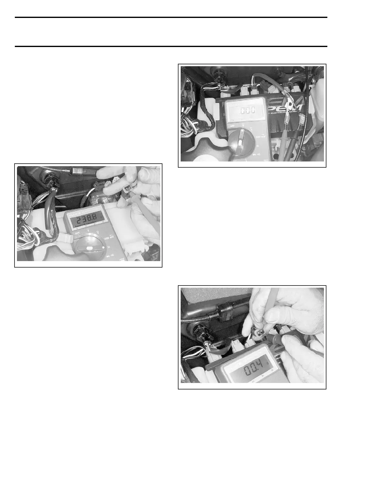
6. MPEM Voltage Testing
– Disconnect the housing between module and
high voltage coil.
– Connect multimeter probes to WHITE/BLUE
and BLACK wires coming out from module.
Place the selector switch to V and the scale to
00.0 Vac.
A32E0ZA
TYPICAL
– Activate the manual starter and check values
indicated by the multimeter.
– Repeat operation 3 times.
– Compare readings with those appearing in the
IGNITION table.
7. High Voltage Coil Testing
Resistance Testing
– Unplug housing between high tension coil and
MPEM.
– Connect multimeter probes to WHITE/BLUE
and BLACK wires and measure resistance.
A32E12A
– Compare readings with those appearing in the
IGNITION table.
Voltage Testing
– Disconnect spark plug cap from spark plug.
– Fasten alligator clip to spark plug cable, near the
spark plug.
278 mmr2004-Rev

 Loading...
