Section 07 ELECTRICAL SYSTEM
Subsection 05 (TESTING PROCEDURE)
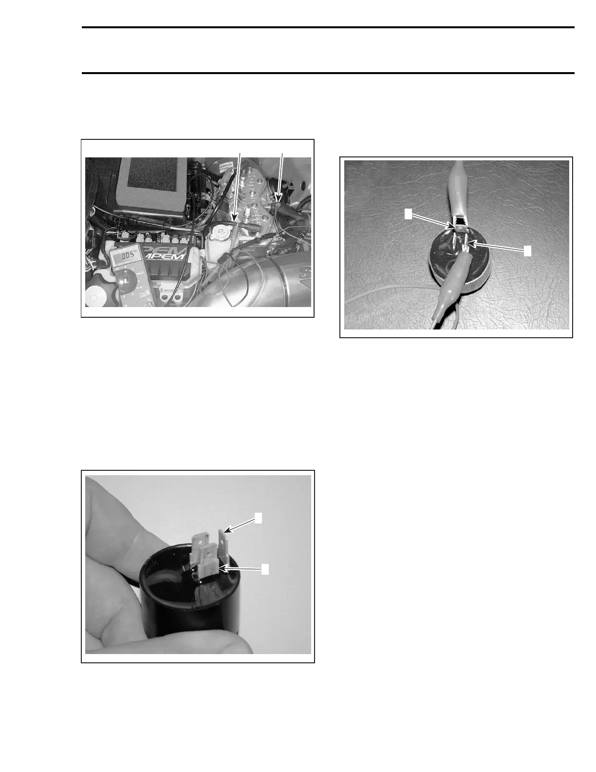
– Connect other multimeter wire to engine
(ground), then place selector switch to V and
scale to 0.00 Vac.
1
A32E11A
2
1. MAG side spark plug cable
2. Connected to ground
– Activate the manual starter and check values
indicated by the multimeter.
– Repeat operation 3 times.
– Compare readings with those appearing in the
IGNITION table.
8. Buzzer Testing
NOTE: Before testing the buzzer, make sure the
connectors are installed on proper buzzer tabs.
A32E3RA
2
1
1. BEIGE/BLACKwireonpositivetab
2. GREEN/REDwireonnegativetab.
Using jumper wires, connect battery positive post
to buzzer positive tab.
Connect battery negative post to buzzer negative
tab. See next photo.
CAUTION: To avoid buzzer damage, ensure
that polarity is respected.
A32E3SA
1
2
TYPICAL — 12-VOLT BATTERY PLUGGED TO BUZZER
1. Buzzer positive tab
2. Buzzer negative tab
A continuous sound should be heard. if not, re-
place the buzzer with a new one.
Lighting Generator Coil Voltage Testing
– Disconnect housing from engine (YELLOW
wires).
– Connect multimeter probes to YELLOW wires,
then place selector switch to V and scale to 0.00
Vac.
– Activate the manual starter and check values
indicated by the multimeter.
– Repeat operation 3 times.
mmr2004-Rev 279

 Loading...
