Section 08 REAR SUSPENSION
Subsection 02 (SC-10 III SUSPENSION)
SHOCK SIZE
SERVICING
TOOL
(P/N)
Piston guide 529 026 600
Seal guide 529 026 500
C-36
Shock wrench 529 035 727
Piston guide 529 035 608
Seal guide
529 035 728
C-46
Shock wrench
529 035 727
Release N (nitrogen) pressure on any HPG T/A
shock with internal floating piston (IFP).
WARNING
Nitrogen gas is under extreme pressure. Use
caution when releasing this gas volume. Pro-
tective eye wear should be used.
All T/A Shock Types
Mount shock in a vise with HPG shock holding tool
(P/N 529 035 769).
529 035 769
A32F2DA
TireValveTypeShock
Remove tire valve cap and push on center rod of
valve to release gas pressure.
A06F18B
2
1
1. Tire valve
2. Tire valve cap
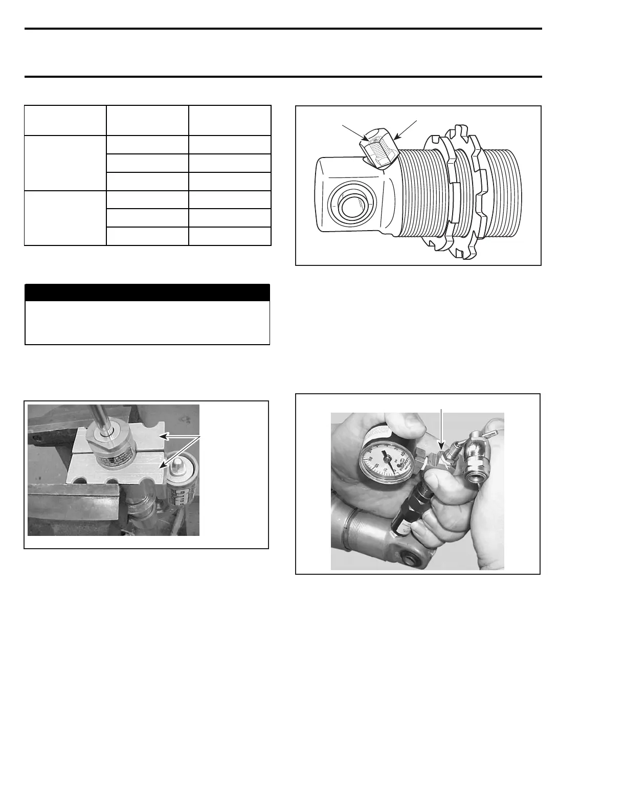
Needle Valve Type Shock
Remove screw on top of valve. Place the needle
guide of gas refill needle type shock tool (P/N 503
190 102) on the shock valve. Press the detent pin
and push forward the needle assembly very slowly
towards rubber of needle valve. Push on shock
tool valve center rod to release gas pressure.
503 190 102
A32F37A
Remove tool from shock.
Screw Cap Types of Shock
Using appropriate size of shock wrench (P/N 529
035 727) unscrew seal carrier.
302 mmr2004-Rev

 Loading...
