Section 12 WIRING DIAGRAM
Subsection 01 (WIRING DIAGRAMS)
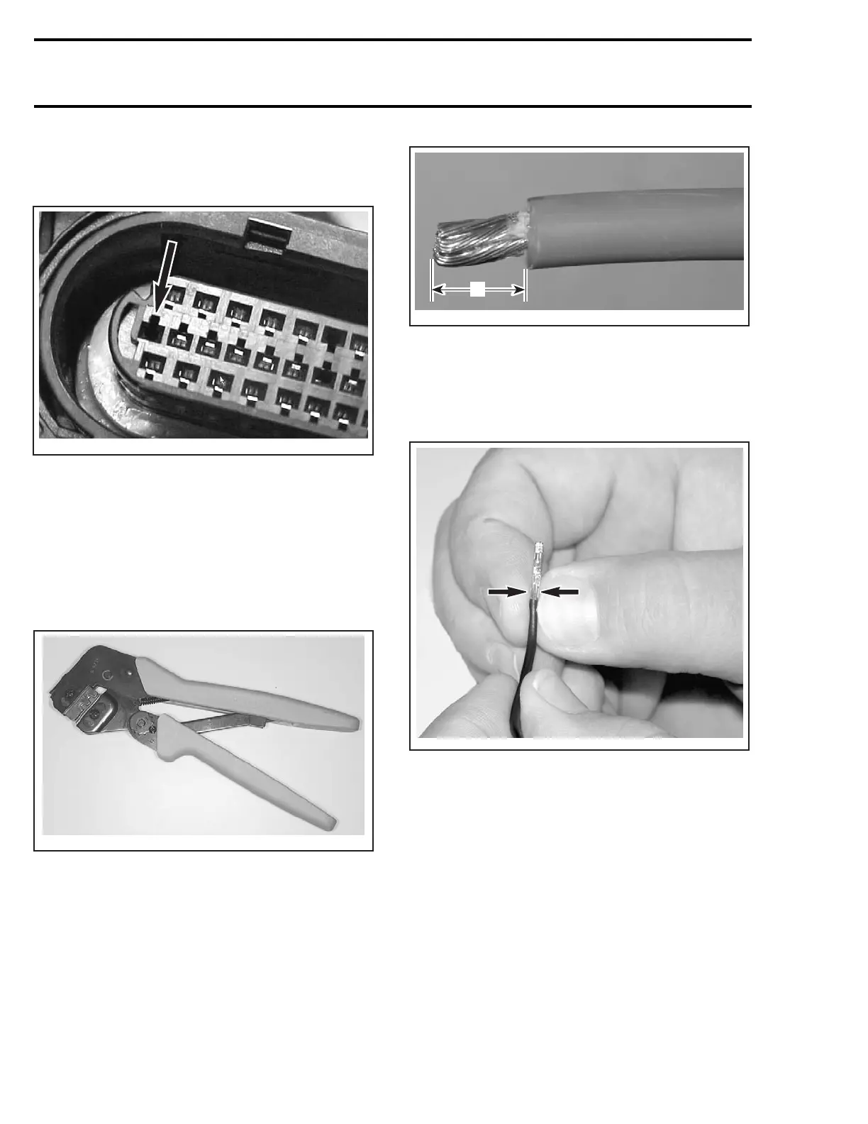
When re-inserting the connector, the locking tab
must be installed facing the smaller cutout of the
connector cavity.
F18Z0XA
Insert the connector, ensuring the locking tab
snaps into the housing.
Re-install the lock, attach the 2 tie raps, and close
the housing cover.
Terminal Crimping (Kostal and AMP multilock)
To crimp a new connector terminal, use the con-
nector crimping tool (P/N 529 035 909) and the
crimper die (P/N 529 035 906).
F00B0EA
CRIMPING TOOL
To properly crimp the wires, strictly follow this pro-
cedure.
Strip the wire to a maximum of 3 mm (1/8 in).
A32E2QA
A
TYPICAL
A. 3mm(1/8in)max.
Position wire in terminal.
Squeeze the terminal tabs with your fingers to
temporarily retain terminal in place.
A32E3YA
Insert terminal with wire in crimping pliers and po-
sition so that top of terminal tabs are flush with
pliers edge or a little bit lower as shown.
418 mmr2004-Rev

 Loading...
