1.6 NetClock 9400 Series Front Panels
1.6.1 NetClock 9483 Front Panel
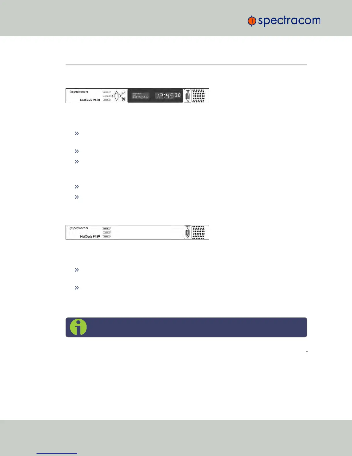
Figure 1-1: NetClock 9483 Series Front Panel Display
The front panel of the NetClock 9483 unit consists of the following:
Three Status LED indicator lights (“Power”, “Sync” and “Fault”); see also "Status LEDs" on
page8.
Keypad buttons, for performing operations from the front panel.
LCD display, showing status information or currently selected menu items (display
options are configurable via the product web interface, such as position information,
time and date, Day of Year, GPS information, network settings, etc.).
LED time display.
An RS-232 serial port interface for serial cable connections.
1.6.2 NetClock 9489 Front Panel
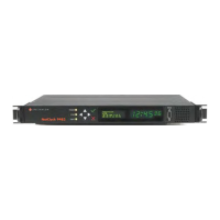
Figure 1-2: NetClock 9489 Front Panel
The front panel of the NetClock 9489 unit consists of the following:
Three Status LED indicator lights (“Power”, “Sync” and “Fault”). See also "Status LEDs"
on page8.
An RS-232 serial port interface connection.
1.6.3 Front Panel Keypad, and Display
Note: This Section applies to NetClock 9483 only.
To simplify operation and to allow local access to NetClock, a keypad and a 4-line LCD inform
ation display are provided on the front panel of the unit.
The front panel keypad and display can be used to configure basic network settings e.g., en-
/disabling DHCP, or setting an IP address and subnet mask.
6
CHAPTER 1 • NetClock User Reference Guide Rev. 16
1.6 NetClock 9400 Series Front Panels