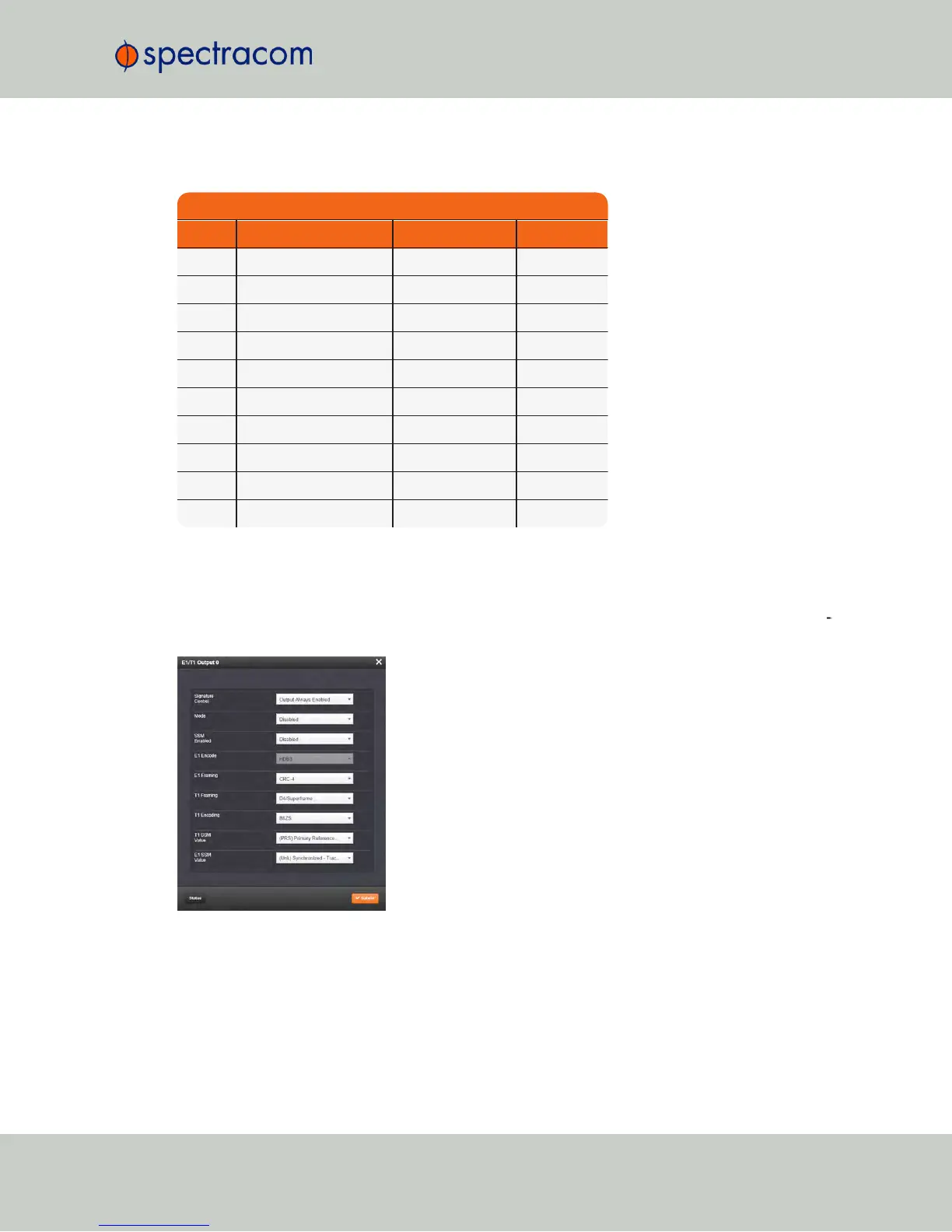
Table 5-10: Option 13
pin assignments
Pin Assignments
Pin No. Signal Function Description
1 GND Ground Ground
2 1.544MHz/2.048MHz RS-485 A Terminal Square wave
3 1.544MHz/2.048MHz RS-485 B Terminal Square wave
4 GND Ground Ground
5 T1/E1 output A1 GR-499/G.703 Tip
6 T1/E1 output B1 GR-499/G.703 Ring
7 GND Ground Ground
8 T1/E1 output A2 GR-499/G.703 Tip
9 T1/E1 output B2 GR-499/G.703 Ring
10 GND Ground Ground
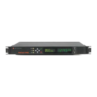
5.2.6.2 E1/T1 Output: Edit Window
To configure an E1/T1 data output , navigate to its Edit window. For instructions, see: "Con
figuring Option Module Inputs/Outputs" on page344.
The Edit window allows the configuration of the following settings:
NetClock User Reference Guide 363
APPENDIX