1.7 NetClock 9400 Series Rear Panels
1.7.1 NetClock 9483 Rear Panel
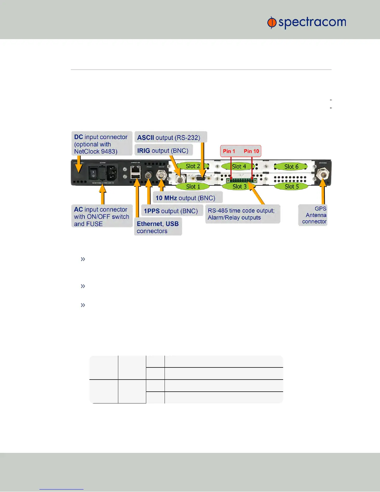
The NetClock 9483 rear panel provides several different outputs for interfacing the unit to vari
ous systems. The rear panel has an ACconnection for power input (DCPower is optional), Eth
ernet and USB connections, 1PPS and 10MHz outputs, IRIG, ASCII, and Relay/Alarm outputs,
and GPS Antenna connector.
Figure 1-4: NetClock 9483 rear panel
AC power connector: Input for the AC power and provides and AC power ON/OFF
switch. This connector is only installed if NetClock was ordered with AC input power
option.
DC power port connector: Only installed if the NetClock was ordered with DC input
power option. Note: DC input power does not have an ON/OFF switch.
Ethernet connector: Provides an interface to the network for NTP synchronization and to
obtain access to the NetClock product web interface for system management. It has two
small indicator lamps, “Good Link” (green LED), and “Activity” (orange LED). The “Good
Link” link light indicates a connection to the network is present. The “Activity” link light
will illuminate when network traffic is detected.
Table 1-2:
Status indicators, rear panel
Ethernet
Yellow
ON LAN activity detected.
OFF No LAN activity detected
Ethernet
Green
ON LAN link established, 10 or 100 Mb/s.
OFF No link established.
10
CHAPTER 1 • NetClock User Reference Guide Rev. 16
1.7 NetClock 9400 Series Rear Panels