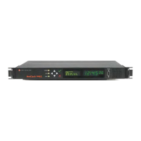
2.7 Connecting the GNSS Input
1.
Install the GNSS antenna, surge suppressor, antenna cabling, and GNSS preamplifier
(if required). Refer to the documentation included with the GNSS antenna for additional
information regarding GNSS antenna installation.
2.
Connect the GNSS cable to the rear panel antenna input jack.
In the event that NO antenna is connected to the rear panel jack, NetClock will—once it
gets powered up (see "Powering Up the Unit" on page224)—activate the Antenna Prob
lem alarm, causing the front panel “Fault” light to be blinking orange (the Antenna Prob
lem alarm indicates an open or short exists in the antenna cable.)
Unless there is an open or short in the antenna cable, the "Fault" light should stop flash
ing orange once the GNSS antenna and coax cable are connected to the rear panel. If
the "Fault" light does not stop flashing after connecting the antenna, refer to
"Troubleshooting GNSS Reception" on page330.
Initial synchronization with GNSS input may take up to 5minutes (approximately) when used
in the default stationary GNSS operating mode. If using GNSS, verify that GNSS is the syn
chronization source by navigating to MANAGEMENT > OTHER: Reference Priority: Confirm
that GNSS is Enabled, and its Status for TIME and 1PPS is valid (green).
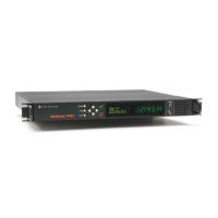
2.8 Connecting Network Cables
NetClock provides a base 10/100 Ethernet port for full NTP functionality, as well as a com
prehensive web-based user interface ("Web UI") for configuration, monitoring and diagnostic
support. Additional network ports are available with the Gigabit Ethernet option module.
First, you need to decide how you want to configure basic network connectivity e.g., the IP
address:
a.
Configure NetClock via the unit's front panel (NetClock 9483 only): See "Setting Up an
IP Address via the Front Panel" on page47.
If your unit does not have a front panel, see "Setting Up a Temporary IP Address
Remotely" on page51.
b.
Configure NetClock by means of a PC connected to an existing network.
When connecting to a hub, router, or network computer, use a straight-through
wired, shielded CAT 5, Cat 5E or CAT 6 cable with RJ-45 connectors. Connect
one end to the Ethernet port on the NetClock rear panel, and the opposite end of
the cable to a network hub or switch.
c.
Configure NetClock by connecting a stand-alone computer directly via a dedicated net
work cable (standard-wired, or crossover cable):
When connecting directly to a stand-alone PC, use a network cable. Connect the
cable to the NIC card of the computer.
Since no DHCP server is available in this configuration both NetClock, and the
PC must be configured with static IP addresses that are on the same subnet
40
CHAPTER 2 • NetClock User Reference Guide Rev. 16
2.7 Connecting the GNSS Input