USB connector is reserved for future expansion.
1PPS output: Provides a once-per-second square-wave output via BNC output connector.
The 1PPS output can be configured to have either the rising or falling edge of the signal
to be coincident with the system’s on-time point.
10 MHz output: Provides a 10 MHz sine-wave output via BNC output connector.
IRIG output: Supports IRIG A/B/G/E, IEEE 1344/C37.118-2005 (AM/TTL).
RS-232 output: for serial connections.
Relay/Alarm outputs.
GNSS antenna connector: GNSS input for GNSSS antenna and coax cabling (type “N”
connector).
RS-485 output for serial connection.
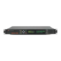
Note: The pin numbers for the RS-485 outputs are defined starting with
Pin1 to Pin10, arranged from left to right, as shown below:
Figure 1-5: Rear panel of NENA-compliant module (NetClock 9483)
1.7.2 NetClock 9489 Rear Panel
The NetClock 9489 rear panel provides:
an AC connection for power input
an Ethernet port
(1) 1PPS output
(2) RS-485 ASCIIoutputs, and (1) RS-485 input
a GNSS antenna connector.
1.7 NetClock 9400 Series Rear Panels
CHAPTER 1 • NetClock User Reference Guide Rev. 16
11