EasyManua.ls Logo

Spectracom NetClock 9489 - Page 368

Default Icon
467 pages
Print Icon
To Next Page IconTo Next Page
To Previous Page IconTo Previous Page
Loading...
Pin Assignments
Figure 5-5: RS-485 connector "J3"
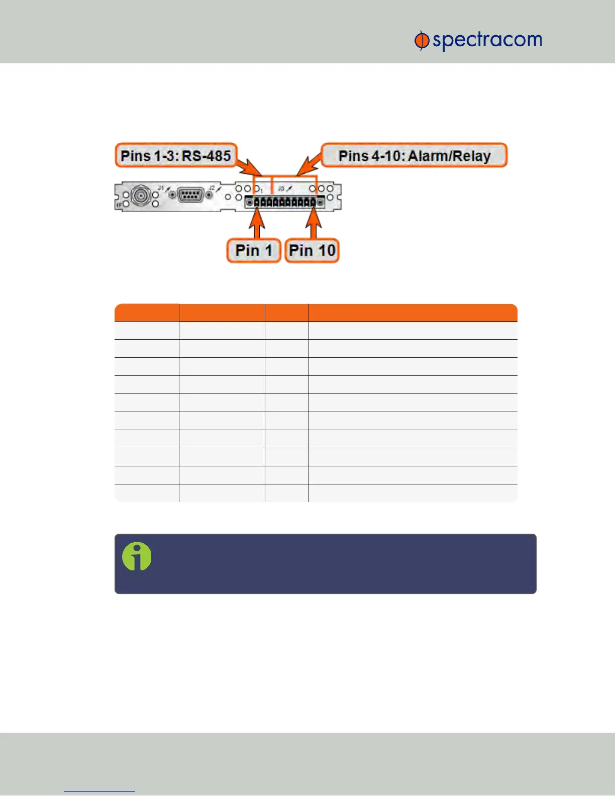
Connector Pin Signal Direction Characteristics
1 RS-485 TX+ Out 0V to 3V
DC
differential, 120 Ω load
2 RS-485 TX- Out 0V to 3V
DC
differential, 120 Ω load
3 GROUND N/A GROUND
4 Relay 1 NO Out Normally Open 30 V
DC
, 2A max.switching power
5 Relay 1 NC Out Normally Closed 30 V
DC
, 2A max.switching power
6 Relay 1 COMMON Out Common Contact 30 V
DC
, 2A max.switching power
7 Relay 2 NO Out Normally Open 30 V
DC
, 2A max.switching power
8 Relay 2 NC Out Normally Closed 30 V
DC
, 2A max.switching power
9 Relay 2 COMMON Out Common Contact 30 V
DC
, 2A max.switching power
10 GROUND N/A GROUND
Table 5-9:
Relay/RS-485 outputs pin assignments
Note: The last device on each of the RS-485 remote output should be terminated
into 120Ω. Auxiliary Spectracom equipment (such as wall display clocks) include
a 120Ω resistor for termination.
352 NetClock User Reference Guide
APPENDIX

Table of Contents

Related product manuals