Controller area network (bxCAN) RM0090
1080/1731 DocID018909 Rev 11
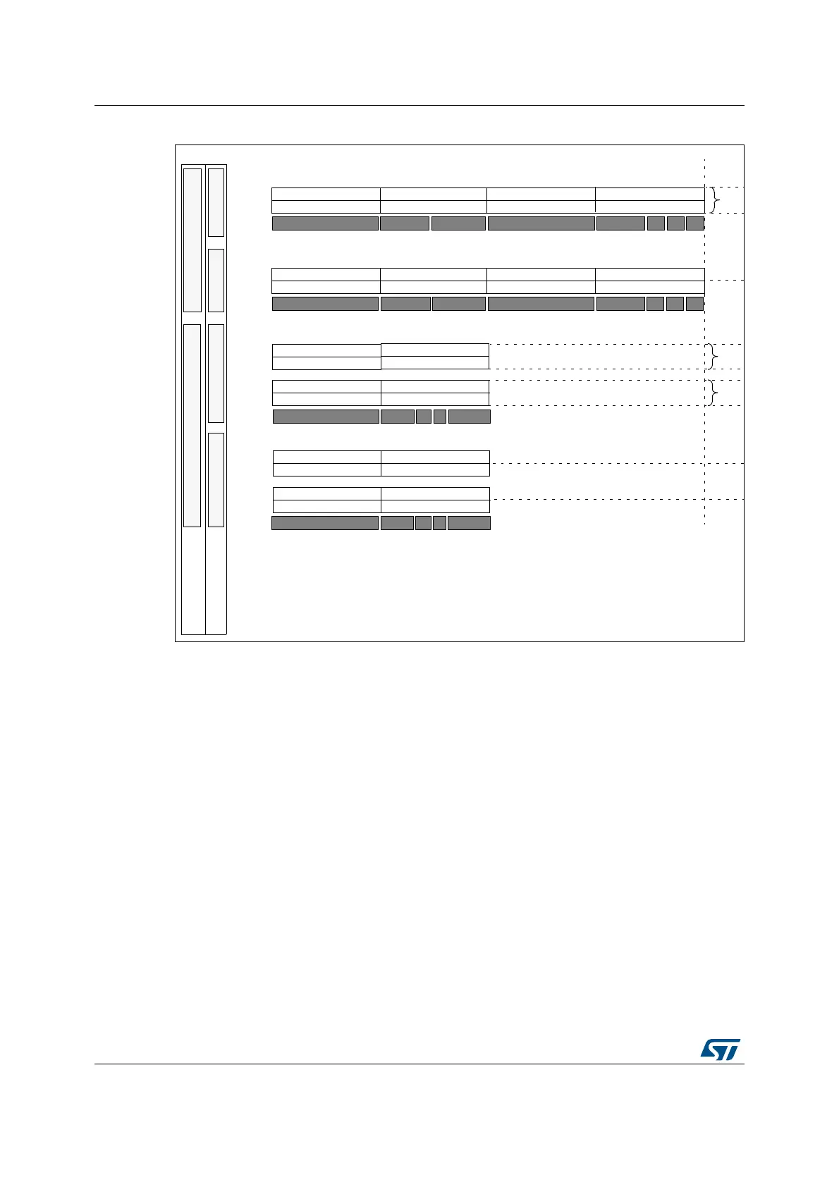
Figure 342. Filter bank scale configuration - register organization
Filter match index
Once a message has been received in the FIFO it is available to the application. Typically,
application data is copied into SRAM locations. To copy the data to the right location the
application has to identify the data by means of the identifier. To avoid this, and to ease the
access to the SRAM locations, the CAN controller provides a Filter Match Index.
This index is stored in the mailbox together with the message according to the filter priority
rules. Thus each received message has its associated filter match index.
The Filter Match index can be used in two ways:
• Compare the Filter Match index with a list of expected values.
• Use the Filter Match Index as an index on an array to access the data destination
location.
For nonmasked filters, the software no longer has to compare the identifier.
If the filter is masked the software reduces the comparison to the masked bits only.
The index value of the filter number does not take into account the activation state of the
filter banks. In addition, two independent numbering schemes are used, one for each FIFO.
Refer to Figure 343 for an example.
One 32-Bit Filter - Identifier Mask
Two 16-Bit Filters - Identifier Mask
CAN_FxR1[31:24]
CAN_FxR2[31:24]
CAN_FxR1[15:8]
CAN_FxR1[31:24]
CAN_FxR1[7:0]
CAN_FxR1[23:16]
x = filter bank number
FSCx = 1FSCx = 0
1
These bits are located in the CAN_FS1R register
Filter Bank Scale
ID
Mask
ID
Mask
STID[10:3]
STID[2:0]
EXID[12:5]
Mapping
STID[10:3]
ID
Mask
Mapping
RTR
Two 32-Bit Filters - Identifier List
ID
ID
STID[10:3] STID[2:0] EXID[12:5]
Mapping
Four 16-Bit Filters - Identifier List
ID
ID
STID[10:3]
ID
ID
Mapping
n
n+1
n+2
n+3
n+1
Filter Bank Mode
2
n
n
n+1
EXID[4:0] IDE
EXID[17:13]
EXID[17:13]
STID[2:0] RTR IDE EXID[17:15]
FBMx = 0FBMx = 1
Filter
2
These bits are located in the CAN_FM1R register
n
Num.
FBMx = 0FBMx = 1
Config. Bits
1
STID[2:0] RTR IDE EXID[17:15]
0
RTREXID[4:0] IDE 0
CAN_FxR1[23:16] CAN_FxR1[15:8] CAN_FxR1[7:0]
CAN_FxR2[7:0]CAN_FxR2[15:8]CAN_FxR2[23:16]
CAN_FxR1[31:24]
CAN_FxR2[31:24]
CAN_FxR1[23:16] CAN_FxR1[15:8] CAN_FxR1[7:0]
CAN_FxR2[7:0]CAN_FxR2[15:8]CAN_FxR2[23:16]
CAN_FxR2[15:8]
CAN_FxR2[31:24]
CAN_FxR2[7:0]
CAN_FxR2[23:16]
CAN_FxR1[15:8]
CAN_FxR1[31:24]
CAN_FxR1[7:0]
CAN_FxR1[23:16]
CAN_FxR2[15:8]
CAN_FxR2[31:24]
CAN_FxR2[7:0]
CAN_FxR2[23:16]
ID=Identifier