DocID018909 Rev 11 385/1731
RM0090 Interrupts and events
389
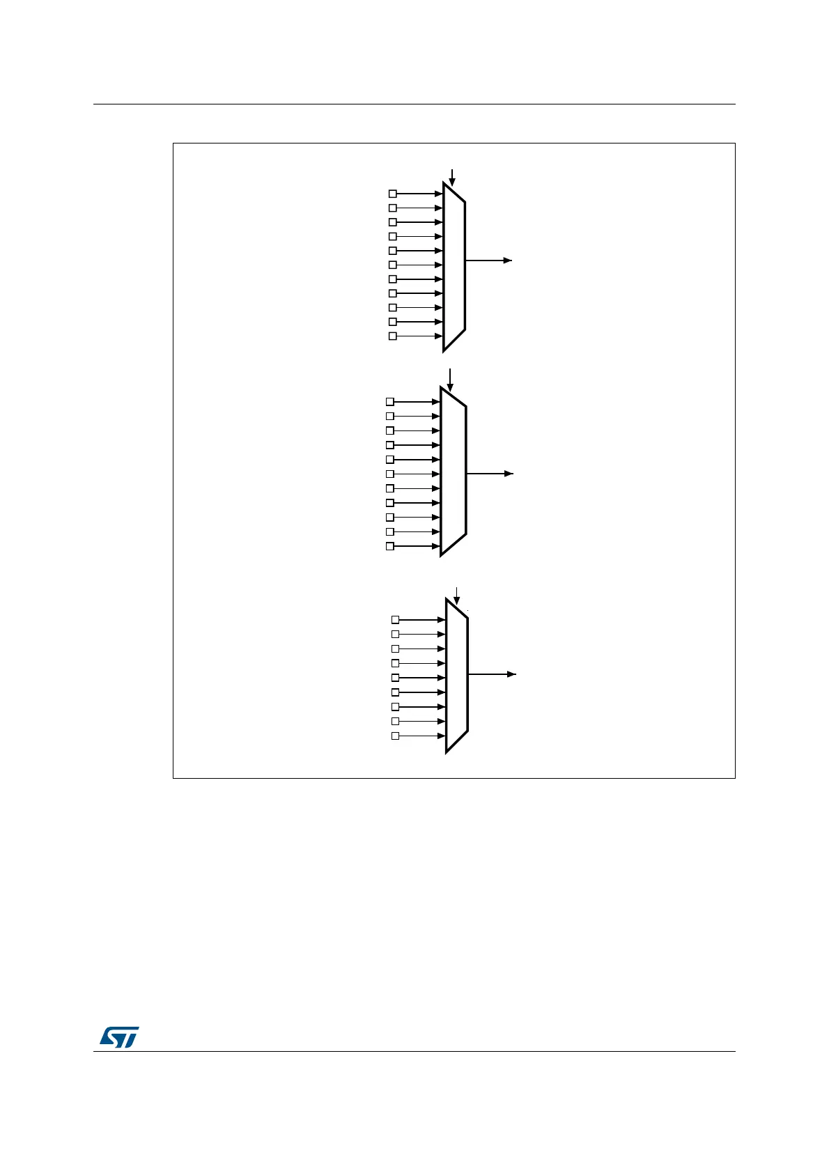
Figure 43. External interrupt/event GPIO mapping (STM32F42xxx and STM32F43xxx)
The seven other EXTI lines are connected as follows:
• EXTI line 16 is connected to the PVD output
• EXTI line 17 is connected to the RTC Alarm event
• EXTI line 18 is connected to the USB OTG FS Wakeup event
• EXTI line 19 is connected to the Ethernet Wakeup event
• EXTI line 20 is connected to the USB OTG HS (configured in FS) Wakeup event
• EXTI line 21 is connected to the RTC Tamper and TimeStamp events
• EXTI line 22 is connected to the RTC Wakeup event
3$
3%
3&
3'
3(
3)
3*
3+
3,
3$
3%
3&
3'
3(
3)
3*
3+
3,
3$
3%
3&
3'
3(
3)
3*
3+
(;7,
(;7,
(;7,
(;7,>@ELWVLQWKH6<6&)*B(;7,&5UHJLVWHU
(;7,>@ELWVLQWKH6<6&)*B(;7,&5UHJLVWHU
(;7,>@ELWVLQWKH6<6&)*B(;7,&5UHJLVWHU
069
3-
3.
3-
3.
3-