DocID018909 Rev 11 891/1731
RM0090 Serial peripheral interface (SPI)
918
28.4 I
2
S functional description
28.4.1 I
2
S general description
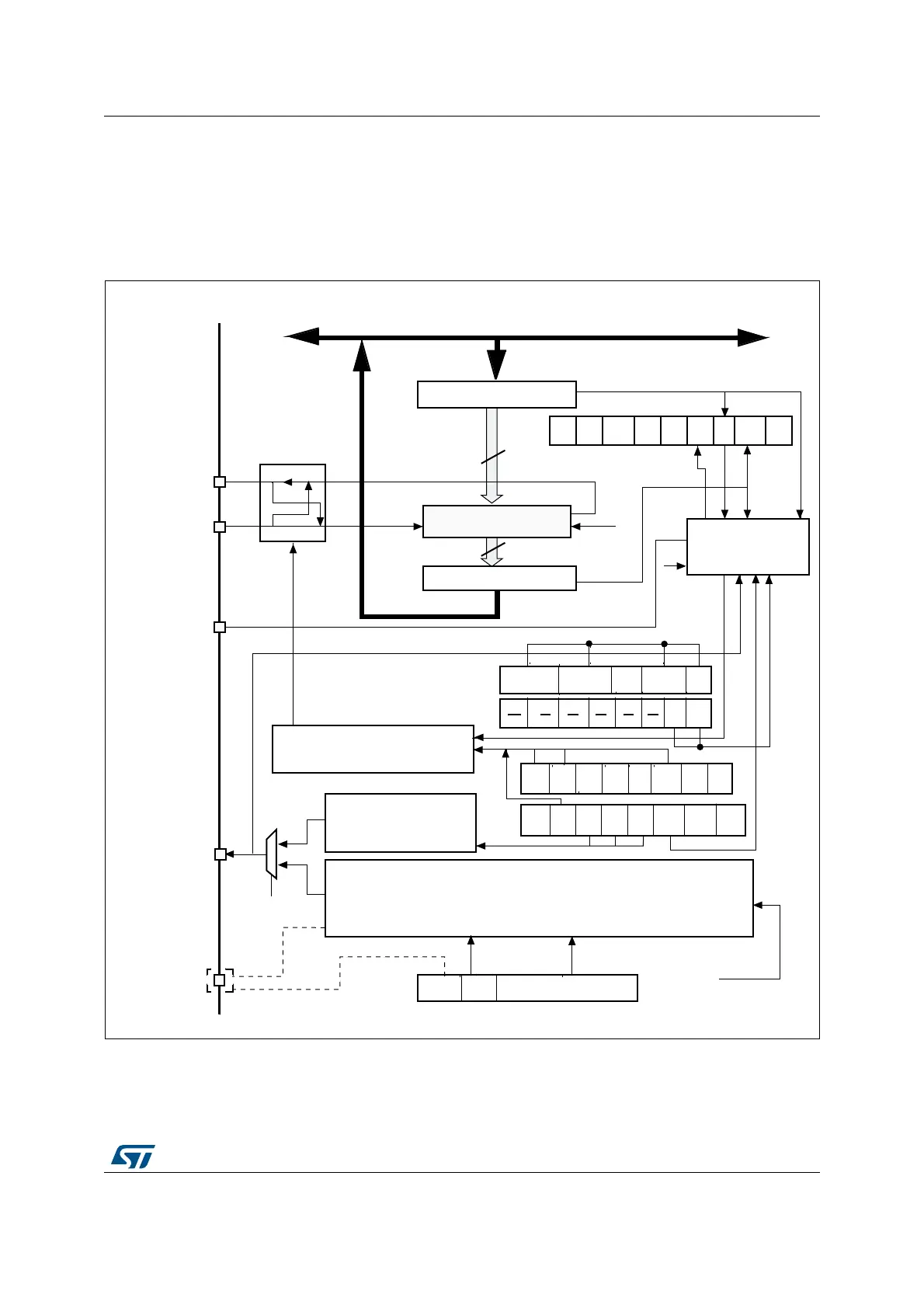
The block diagram of the I
2
S is shown in Figure 262.
Figure 262. I
2
S block diagram
1. I2S2ext_SD and I2S3ext_SD are the extended SD pins that control the I
2
S full duplex mode.
The SPI could function as an audio I
2
S interface when the I
2
S capability is enabled (by
setting the I2SMOD bit in the SPI_I2SCFGR register). This interface uses almost the same
pins, flags and interrupts as the SPI.
4XBUFFER
3HIFTREGISTER
BIT
#OMMUNICATION
2XBUFFER
BIT
-/3) 3$
-ASTERCONTROLLOGIC
-)3/
)3EXT?3$
)3EXT?3$
30)
BAUDRATEGENERATOR
#+
)3-/$
,3"FIRST
,3"
&IRST
30% "2 "2 "2
-342 #0/, #0(!
"IDI
MODE
"IDI
/%
#2#
%.
#2#
.EXT
$&&
2X
ONLY
33-
33)
!DDRESSANDDATABUS
CONTROL
.3373
"39 /62 -/$&
#2#
%22
#(
3)$%
4X% 2X.%
)
3CLOCKGENERATOR
-#+
)3?#+
)3
-/$
)3%
#(
$!4,%.
,%.
#+
0/,
)3#&' )334$
-#+/%/$$ )3$)6;=
;= ;=
;=
5$2
)3X#,+
-36
&2%