Basic timers (TIM6&TIM7) RM0090
690/1731 DocID018909 Rev 11
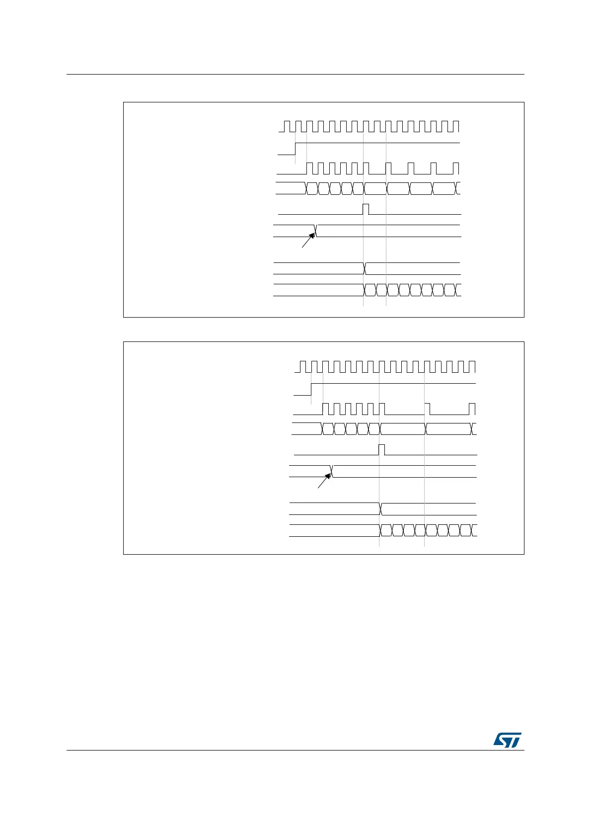
Figure 204. Counter timing diagram with prescaler division change from 1 to 2
Figure 205. Counter timing diagram with prescaler division change from 1 to 4
20.3.2 Counting mode
The counter counts from 0 to the auto-reload value (contents of the TIMx_ARR register),
then restarts from 0 and generates a counter overflow event.
An update event can be generate at each counter overflow or by setting the UG bit in the
TIMx_EGR register (by software or by using the slave mode controller).
The UEV event can be disabled by software by setting the UDIS bit in the TIMx_CR1
register. This avoids updating the shadow registers while writing new values into the preload
registers. In this way, no update event occurs until the UDIS bit has been written to 0,
however, the counter and the prescaler counter both restart from 0 (but the prescale rate
does not change). In addition, if the URS (update request selection) bit in the TIMx_CR1
CK_PSC
00
CNT_EN
Timer clock = CK_CNT
Counter register
Update event (UEV)
0
F9 FA FB FCF7
Prescaler control register
01
Write a new value in TIMx_PSC
01 02 03
Prescaler buffer
01
Prescaler counter
0
1 0 1 0 1 0 1
F8
CK_PSC
00
CNT_EN
Timer clock = CK_CNT
Counter register
Update event (UEV)
0
F9 FA FB FCF7
Prescaler control register
03
Write a new value in TIMx_PSC
Prescaler buffer
03
Prescaler counter
0
1 2 3 0 1 2 3
F8 01