DocID018909 Rev 11 739/1731
RM0090 Cryptographic processor (CRYP)
757
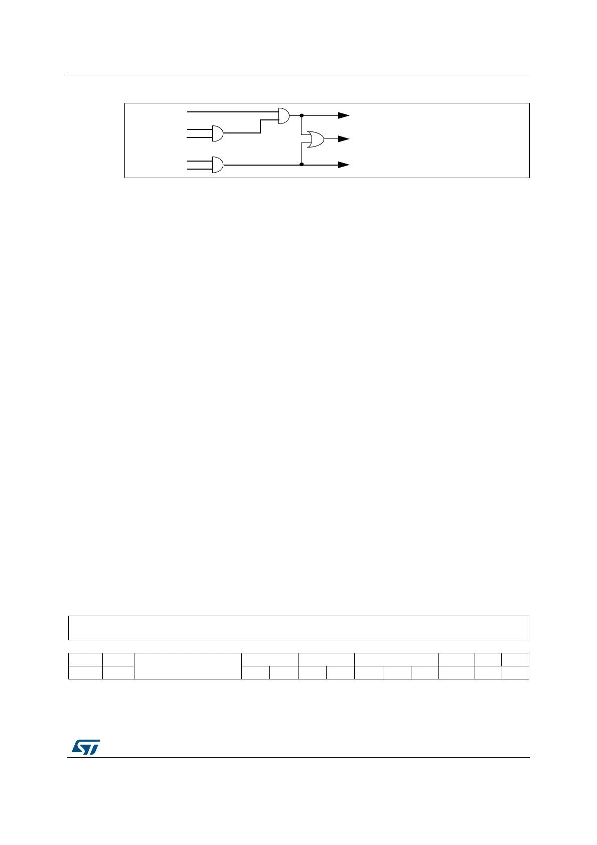
Figure 231. CRYP interrupt mapping diagram
23.5 CRYP DMA interface
The cryptographic processor provides an interface to connect to the DMA controller. The
DMA operation is controlled through the CRYP DMA control register, CRYP_DMACR.
The burst and single transfer request signals are not mutually exclusive. They can both be
asserted at the same time. For example, when there are 6 words available in the OUT FIFO,
the burst transfer request and the single transfer request are asserted. After a burst transfer
of 4 words, the single transfer request only is asserted to transfer the last 2 available words.
This is useful for situations where the number of words left to be received in the stream is
less than a burst.
Each request signal remains asserted until the relevant DMA clear signal is asserted. After
the request clear signal is deasserted, a request signal can become active again, depending
on the above described conditions. All request signals are deasserted if the CRYP
peripheral is disabled or the DMA enable bit is cleared (DIEN bit for the IN FIFO and DOEN
bit for the OUT FIFO in the CRYP_DMACR register).
Note: The DMA controller must be configured to perform burst of 4 words or less. Otherwise some
data could be lost.
In order to let the DMA controller empty the OUT FIFO before filling up the IN FIFO, the
OUTDMA channel should have a higher priority than the INDMA channel.
23.6 CRYP registers
The cryptographic core is associated with several control and status registers, eight key
registers and four initialization vectors registers.
23.6.1 CRYP control register (CRYP_CR) for STM32F415/417xx
Address offset: 0x00
Reset value: 0x0000 0000
).2)3
).)-
#290%.
).-)3
).&)&/)NTERRUPT).-)3
/542)3
/54)-
/54-)3
/54&)&/)NTERRUPT/54-)3
'LOBAL)NTERRUPT
AI
31 30 29 28 27 26 25 24 23 22 21 20 19 18 17 16
Reserved
15 14 13 12 11 10 9 8 76543 2 10
CRYPEN FFLUSH
Reserved
KEYSIZE DATATYPE ALGOMODE[2:0] ALGODIR Res. Res.
rw w rw rw rw rw rw rw rw rw

 Loading...