DocID018909 Rev 11 929/1731
RM0090 Serial audio interface (SAI)
957
The master clock may be generated externally on an I/O pad for external decoders if the
corresponding audio block is declared as master with bit NODIV = 0 in the SAI_xCR1
register. In slave, the value set in this last bit is ignored since the clock generator is OFF,
and the MCLK_x I/O pin is released for use as a general purpose I/O.
The bit clock is derived from the master clock. The bit clock divider sets the divider factor
between the bit clock SCK_x and the master clock MCLK_x following the formula:
SCK_x = MCLK x (FRL[7:0] +1) / 256
where:
256 is the fixed ratio between MCLK and the audio frequency sampling.
FRL[7:0] is the number of bit clock - 1 in the audio frame, configured in the SAI_xFRCR
register.
It is mandatory in master mode that (FRL[7:0] +1) should be equal to a number with a power
of 2 (refer to Section 29.7) in order to have an even integer number of MCLK_x pulses by bit
clock. The 50% duty cycle is guaranteed on the bit clock SCK_x.
The SAI_CK_x clock can be also equal to the bit clock frequency. In this case, bit NODIV in
the SAI_xCR1 register should be set and the value inside the MCKDIV divider and the bit
clock divider will be ignored. In this case, the number of bits per frame is fully configurable
without the need to be equal to a power of two.
The bit clock strobing edge on SCK can be configured by bit CKSTR in the SAI_xCR1
register.
29.10 Internal FIFOs
Each audio block in the SAI has its own FIFO. Depending if the block is defined to be a
transmitter or a receiver, the FIFO will be written or read, respectively. There is therefore
only one FIFO request linked to FREQ bit in the SAI_xSR register.
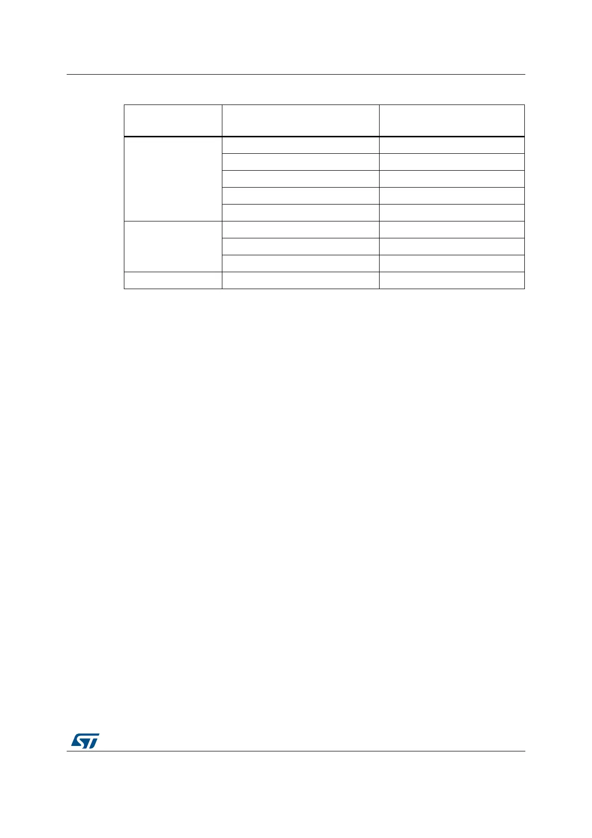
Table 129. Example of possible audio frequency sampling range
Input SAI_CK_x clock
frequency
Most usual audio frequency
sampling achievable
MCKDIV[3:0]
192 kHz x 256
192 kHz MCKDIV[3:0] = 0000
96 kHz MCKDIV[3:0] = 0001
48 kHz MCKDIV[3:0] = 0010
16 kHz MCKDIV[3:0] = 0100
8 kHz MCKDIV[3:0] = 1000
44.1 kHz x 256
44.1 kHz MCKDIV[3:0] = 0000
22.05 kHz MCKDIV[3:0] = 0001
11.025 kHz MCKDIV[3:0] = 0010
SAI_CK_x = MCLK
(1)
1. This may happen when the product clock controller selects an external clock source, instead of PLL clock.
MCLK MCKDIV[3:0] = 0000