DMA controller (DMA) RM0090
306/1731 DocID018909 Rev 11
10.3 DMA functional description
10.3.1 General description
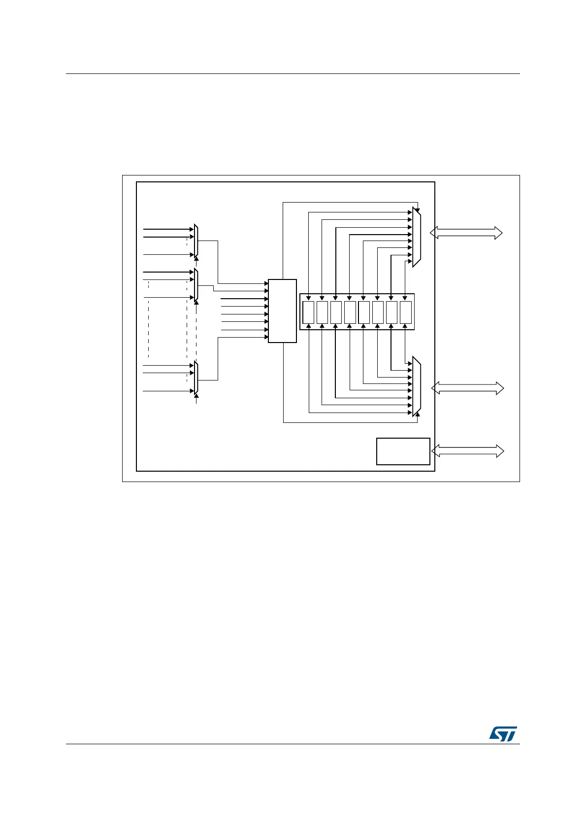
Figure 32 shows the block diagram of a DMA.
Figure 32. DMA block diagram
The DMA controller performs direct memory transfer: as an AHB master, it can take the
control of the AHB bus matrix to initiate AHB transactions.
It can carry out the following transactions:
• peripheral-to-memory
• memory-to-peripheral
• memory-to-memory
The DMA controller provides two AHB master ports: the AHB memory port, intended to be
connected to memories and the AHB peripheral port, intended to be connected to
peripherals. However, to allow memory-to-memory transfers, the AHB peripheral port must
also have access to the memories.
The AHB slave port is used to program the DMA controller (it supports only 32-bit
accesses).
See Figure 33 and Figure 34 for the implementation of the system of two DMA controllers.
AHB master
Memory port
FIFO
AHB master
Peripheral port
STREAM 0
FIFO
STREAM 1
STREAM 0
STREAM 1
FIFO
STREAM 2STREAM 2
FIFO
STREAM 7
STREAM 7
REQ_STREAM0
REQ_STR0_CH0
REQ_STR0_CH1
DMA controller
FIFO
STREAM 3STREAM 3
FIFO
STREAM 4STREAM 4
FIFO
STREAM 5STREAM 5
FIFO
STREAM 6STREAM 6
Arbiter
REQ_STREAM1
REQ_STREAM2
REQ_STREAM3
REQ_STREAM4
REQ_STREAM5
REQ_STREAM6
REQ_STREAM7
REQ_STR0_CH7
REQ_STR1_CH0
REQ_STR1_CH1
REQ_STR1_CH7
REQ_STR7_CH0
REQ_STR7_CH1
REQ_STR7_CH7
AHB slave
programming
interface
Programming port
Channel
selection
ai15945