LCD-TFT Controller (LTDC) RM0090
482/1731 DocID018909 Rev 11
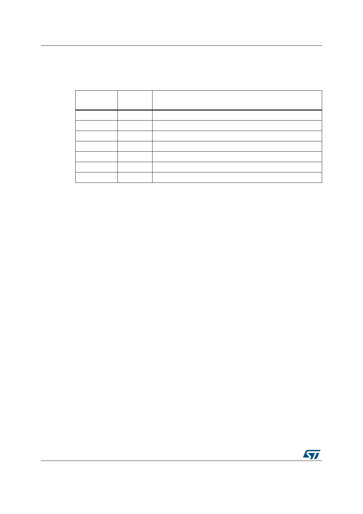
16.3.3 LCD-TFT pins and signal interface
The Table below summarizes the LTDC signal interface:
The LCD-TFT controller pins must be configured by the user application. The unused pins
can be used for other purposes.
For LTDC outputs up to 24-bit (RGB888), if less than 8bpp are used to output for example
RGB565 or RGB666 to interface on 16b-bit or 18-bit displays, the RGB display data lines
must be connected to the MSB of the LCD-TFT controller RGB data lines. As an example, in
the case of an LCD-TFT controller interfacing with a RGB565 16-bit display, the LCD display
R[4:0], G[5:0] and B[4:0] data lines pins must be connected to LCD-TFT controller
LCD_R[7:3], LCD_G[7:2] and LCD_B[7:3].
16.4 LTDC programmable parameters
The LCD-TFT controller provides flexible configurable parameters. It can be enabled or
disabled through the LTDC_GCR register.
16.4.1 LTDC Global configuration parameters
Synchronous Timings:
Figure 82 presents the configurable timing parameters generated by the Synchronous
Timings Generator block presented in the block diagram Figure 81. It generates the
Horizontal and Vertical Synchronization timings panel signals, the Pixel Clock and the Data
Enable signals.
Table 88. LCD-TFT pins and signal interface
LCD-TFT
signals
I/O Description
LCD_CLK O Clock Output
LCD_HSYNC O Horizontal Synchronization
LCD_VSYNC O Vertical Synchronization
LCD_DE O Data Enable
LCD_R[7:0] O Data: 8-bit Red data
LCD_G[7:0] O Data: 8-bit Green data
LCD_B[7:0] O Data: 8-bit Blue data