DocID018909 Rev 11 1091/1731
RM0090 Controller area network (bxCAN)
1112
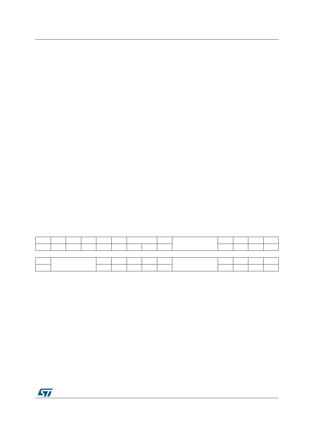
CAN transmit status register (CAN_TSR)
Address offset: 0x08
Reset value: 0x1C00 0000
Bit 2 ERRI: Error interrupt
This bit is set by hardware when a bit of the CAN_ESR has been set on error detection and
the corresponding interrupt in the CAN_IER is enabled. Setting this bit generates a status
change interrupt if the ERRIE bit in the CAN_IER register is set.
This bit is cleared by software.
Bit 1 SLAK: Sleep acknowledge
This bit is set by hardware and indicates to the software that the CAN hardware is now in
Sleep mode. This bit acknowledges the Sleep mode request from the software (set SLEEP
bit in CAN_MCR register).
This bit is cleared by hardware when the CAN hardware has left Sleep mode (to be
synchronized on the CAN bus). To be synchronized the hardware has to monitor a
sequence of 11 consecutive recessive bits on the CAN RX signal.
Note: The process of leaving Sleep mode is triggered when the SLEEP bit in the CAN_MCR
register is cleared. Please refer to the AWUM bit of the CAN_MCR register description
for detailed information for clearing SLEEP bit
Bit 0 INAK
: Initialization acknowledge
This bit is set by hardware and indicates to the software that the CAN hardware is now in
initialization mode. This bit acknowledges the initialization request from the software (set
INRQ bit in CAN_MCR register).
This bit is cleared by hardware when the CAN hardware has left the initialization mode (to
be synchronized on the CAN bus). To be synchronized the hardware has to monitor a
sequence of 11 consecutive recessive bits on the CAN RX signal.
31 30 29 28 27 26 25 24 23 22 21 20 19 18 17 16
LOW2 LOW1 LOW0 TME2 TME1 TME0 CODE[1:0] ABRQ2
Reserved
TERR2 ALST2 TXOK2 RQCP2
rrrrrrrrrs rc_w1rc_w1rc_w1rc_w1
1514131211109876543210
ABRQ1
Reserved
Res.
TERR1 ALST1 TXOK1 RQCP1 ABRQ0
Reserved
TERR0 ALST0 TXOK0 RQCP0
rs rc_w1 rc_w1 rc_w1 rc_w1 rs rc_w1 rc_w1 rc_w1 rc_w1
Bit 31 LOW2: Lowest priority flag for mailbox 2
This bit is set by hardware when more than one mailbox are pending for transmission and
mailbox 2 has the lowest priority.
Bit 30 LOW1
: Lowest priority flag for mailbox 1
This bit is set by hardware when more than one mailbox are pending for transmission and
mailbox 1 has the lowest priority.
Bit 29 LOW0
: Lowest priority flag for mailbox 0
This bit is set by hardware when more than one mailbox are pending for transmission and
mailbox 0 has the lowest priority.
Note: The LOW[2:0] bits are set to zero when only one mailbox is pending.
Bit 28 TME2
: Transmit mailbox 2 empty
This bit is set by hardware when no transmit request is pending for mailbox 2.
Bit 27 TME1
: Transmit mailbox 1 empty
This bit is set by hardware when no transmit request is pending for mailbox 1.