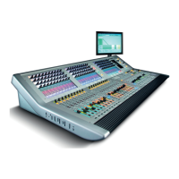
Vista 1 Digital Mixing System
2-6 Desk Operation
Document generated: 18.04.17
SW V5.3
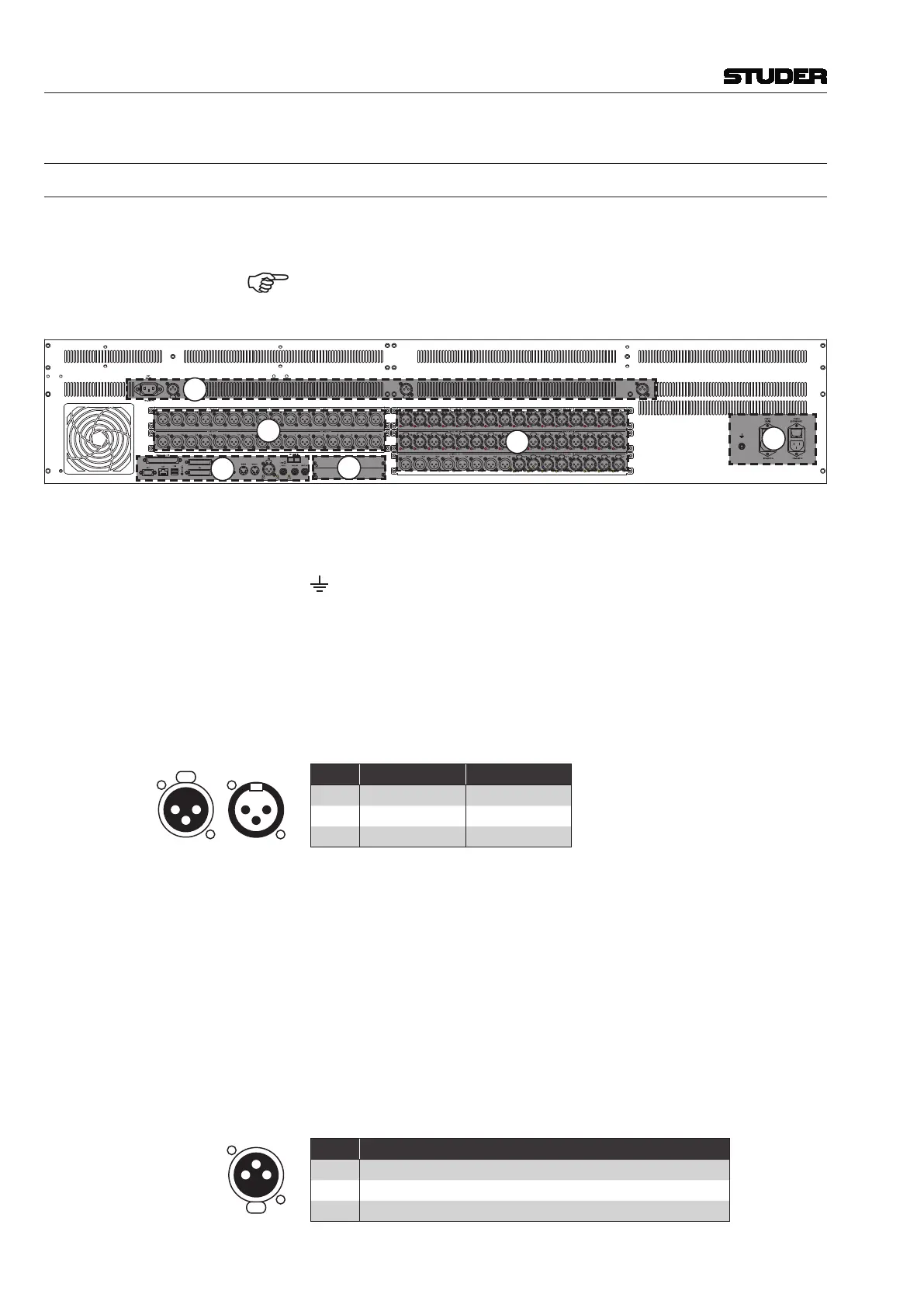
2.1.4 Connectors
2.1.4.1 Rear Panel Connectors
Due to the fact that Vista 1 is an all-in-one console, wiring is somewhat easier
since no connection(s) to any external DSP core need to be made. There are
six connector areas at the console’s rear side.
Connectors dedicated to monitoring and talkback inputs/outputs are some-
what depending on the currently loaded DSP configuration (details on con-
figurations: chapter 6; connection details: chapter 2.1.5).
1
3
2
4
5
6
(1) POWER (MAIN) and POWER (REDUNDANT) Mains inputs on IEC320/C13
appliance inlets with integrated power switches. Two separate, wide-range
input power supplies are built into the desk for supply redundancy, and
Ground terminal with M6 thread.
(2) MIC/LINE IN: 32 analog, electronically balan ced microphone/line level inputs
on XLR3m connectors; a red LED per input indicates if the 48 V phantom
power is switched on, and
AES/EBU IN / AES/EBU OUT: 8 digital AES/EBU input/output pairs on
XLR3m/f connectors; a green LED per input indicates lock status.
(3) LINE OUT: 32 analog, electronically balanced line level outputs on XLR3f
connectors.
1
3
2
2
3
1
Pin Signal (Input) Signal (Output)
1 Screen Screen
2 In + Out +
3 In – Out –
(4) Two slots for Studer D21m I/O extension cards, accommodating either one
double-width or two single-width cards.
If an additional Compact Stagebox is connected, an optical or twisted-pair
D21m MADI card is used here, matching the MADI HD card in the Compact
Stagebox.
(5) Area of different additional audio, communication and control signal inputs/
outputs. For details refer to chapter 5.1.1.
(6) OUT (MAIN) Mains output for the external GC monitor screen on an IEC320/
C14 appliance outlet; it is directly connected to the MAIN power inlet and
so always has the same voltage, and
Three XLR3f sockets for connecting gooseneck console lighting (not
included). Voltage is 5 or 12 VDC, selectable with an internal jumper.
1
3
2
Pin Signal
1 n.c.
2 +5 VDC or +12 VDC (factory default: 12 V), 1 A max. per socket
3 GND