Vista 1 Digital Mixing System
Desk Operation 2-7
Document generated: 18.04.17
SW V5.3
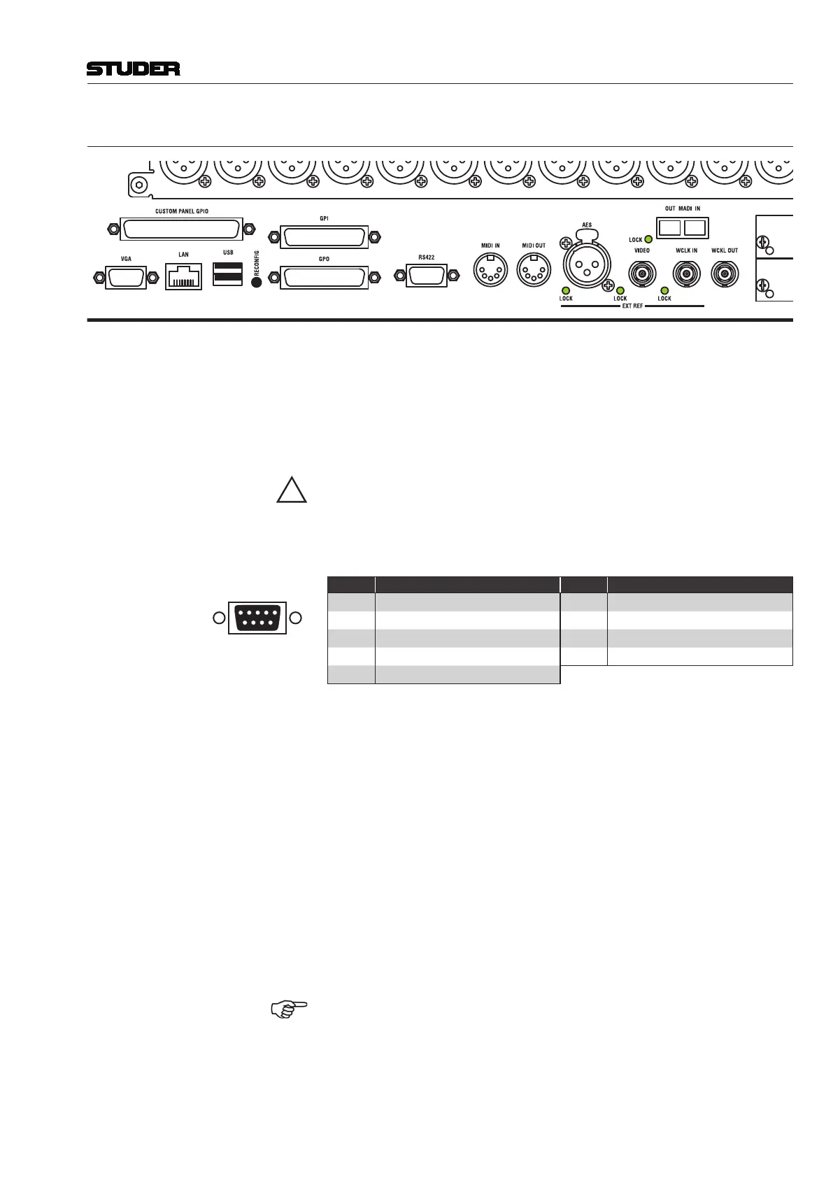
2.1.4.1.1 Connector Area 5
VGA Connector for the external graphical controller screen.
LAN Ethernet port for communication with the console’s control system.
USB Dual USB port for connecting an external keyboard (and a mouse, if required)
or a memory device for backup purposes to the console’s control system.
These ports are equivalent to the DATA USB port on the desk.
A USB memory device MUST NOT BE UNPLUGGED DURING DATA
ACCESS – only remove it after its LED has stopped flashing in order to
avoid data loss!
RS422 9-pin D-type connector (female, UNC 4-40 thread) for RS422 communication
with the console’s control system (COM 4).
15
9 6
Solder/Crimp View
(or Socket View)
Pin Signal Pin Signal
1 n.c. 6 n.c.
2 RX– 7 RX+
3 TX+ 8 TX–
4 n.c. 9 n.c.
5 n.c.
MIDI IN / MIDI OUT MIDI control input/output on MIDI-standard 5-pin DIN sockets, for use with
external MIDI communication from the Cue List, such as external reverb
preset control.
EXT REF External clock reference inputs:
AES AES/EBU on an XLR3f socket
VIDEO Video reference signal input, termination 75 W or hi-Z selectable with DIP
switch S2-1 on the Central PCB near the connector (switch off = hi-Z, this is
the factory default setting)
WCLK IN Word Clock reference signal input, termination 75 W or hi-Z with DIP switch
S2-4 on the Central PCB near the connector (switch off = hi-Z; this is the
factory default setting)
WCLK OUT Word Clock signal output for operation with the desk’s internal reference.
Output impedance 75 W.
MADI Optical, multimode 64 I/O MADI port (62.5 μm/125 μm SC connector).
This interface is intended as a multi-track I/O. It cannot be used for connect-
ing a stagebox since no control signals for preamp remote control are imple-
mented on this interface.
RECONFIG The recessed RECONFIG key must be pressed after having changed the I/O
module or D21m card configuration.