Vista 1 Digital Mixing System
2-8 Desk Operation
Document generated: 18.04.17
SW V5.3
CUSTOM PANEL GPIO (37-pin D-type, female, UNC 4-40 thread) for wiring the 12-key CUSTOM
PANEL desk section for external tasks such as signaling. The 12 ‘Switch’
control outputs are open collectors pulling to ground if active. They are
controlled by the CUSTOM PANEL GP 1-12 desk keys. The 12 ‘LED’ control
inputs are dedicated to illuminating the corresponding keys. The function of
GPO 7-12 can be modified by pulling pin 34 to ground in such a way that
they are controlled by software (configurable). The GP 7-12 desk keys will
then have no function.
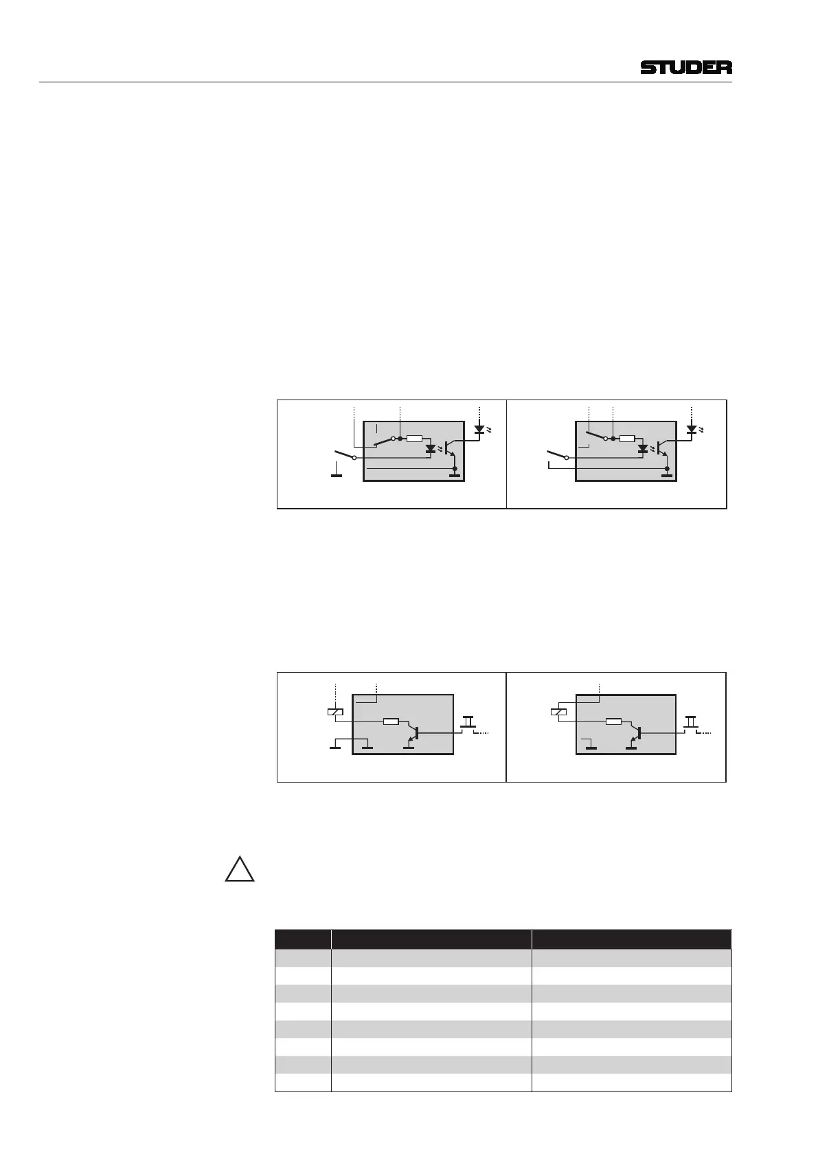
Inputs The two control input groups (LEDs 1-6 and 7-12) are independent. They
may be used either with the internal +5 V DC supply voltage, or with external
voltages of +5...+24 V DC; selection is made with DIP switch S184-1 and
-2 (refer to the tables above). In both cases they are activated by pulling the
LED X input to ground, either to the internal one or the one of the external
supply, respectively.
1 k
Desk
LED x
Ext. Supply
+5 - +24 VDC
LED Grp x...
LED x
Ext. GND
1 k
Desk
LED x
Int. Supply to LED Group
LED x
Int. GND
to LED Group
External Supply Internal Supply
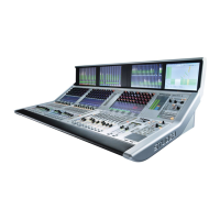
Outputs The control outputs (activated by CUSTOM PANEL GP 1-12 desk keys, or
desk keys GP 1-6 and internal GPO 7-12) are open-collector outputs pulling
to GND if active, with either momentary or latching action; this is selected
with DIP switches S184-3 and -4 and S185 (refer to the tables below).
The +5 V DC supply voltage (or an external supply of up to 24 VDC) together
with the open collector outputs may be used to generate an output signal for
relays, LEDs etc.
22
Desk
Key
Int. Supply
Load
(Relay x)
22
Desk
Key x
Ext.
Supply
Ext. GND
No Int. GND
Load
(Relay x)
External Supply Internal Supply
Current must not exceed 300 mA per output. Please make sure to use appro-
priate current-limiting resistors in series if necessary. When using an external
supply, connect its ground terminal to the internal ground (pins 1 or 19).
The total current supplied by the VCC (+5 V DC) pin of the CUSTOM PANEL
GPIO connector must not exceed 400 mA.
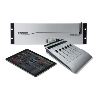
Options are set by DIP switches on the on the Central PCB:
DIP SW ON OFF
S184-1 Int. Supply f. LEDs 1-6 Ext. Supply f. LEDs 1-6, 5-24 V DC
S184-2 Int. Supply f. LEDs 7-12 Ext. Supply f. LEDs 7-12, 5-24 V DC
S184-3 Switch 5, 6 momentary action Switch 5, 6 toggling action
S184-4 Switch 5, 6 momentary action Switch 5, 6 toggling action
S184-5 Switch 1-4 not active at power-up Switch 1-4 active at power-up
S184-6 Switch 7-10 not active at power-up Switch 7-10 active at power-up
S184-7 Switch 5, 6 not active at power-up Switch 5, 6 active at power-up
S184-8 Switch 11, 12 not active at power-up Switch 11, 12 active at power-up