Vista 1 Digital Mixing System
Desk Operation 2-11
Document generated: 18.04.17
SW V5.3
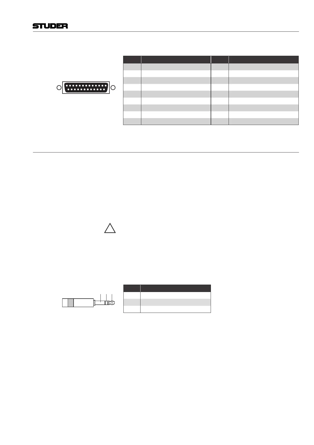
GPO 1-8 (25-pin D-type, female, UNC 4-40 thread)
Solder/Crimp View
(or Socket View)
1
1425
13
Pin
Signal ‘GPO 1-8’ Pin Signal ‘GPO 1-8’
1 GPO 1a 14 GPO 1b
2 GPO 2a 15 GPO 2b
3 GPO 3a 16 GPO 3b
4 GPO 4a 17 GPO 4b
5 GPO 5a 18 GPO 5b
6 GPO 6a 19 GPO 6b
7 GPO 7a 20 GPO 7b
8 GPO 8a 21 GPO 8b
9-13 GND (0 V) 22-25 VCC (+5 V / 600 mA max.)
2.1.4.2 Front Connectors
DATA USB Socket In the SYSTEM Area of the control bay; for data backup and restore purposes
or, e.g., connecting a USB keyboard.
Jingle Player USB Socket Under the desk’s hand rest at the right-hand side; reserved for the integrated
jingle player only. This USB socket may, of course, also be used for an
external hard drive. If this drive takes its power supply from the USB socket,
its consumption must not exceed 500 mA. Supplying the unit externally is
strongly recommended.
A USB memory device MUST NOT BE UNPLUGGED DURING DATA
ACCESS – only remove it after its LED has stopped flashing in order to
avoid data loss!
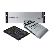
Headphones Socket Under the desk’s hand rest at the right-hand side; this is a standard 6.35 mm
TRS headphones socket. Recommended headphones impedance 75 - 300 W.
Headphones with higher and lower impedances may be used but will produce
reduced listening level.
Pin Signal
Tip Left Channel
Ring Right Channel
Sleeve Screen/GND