121
DISPLAYING TOMOGRAMS
3.9. Pin-point Registration™
3.9.1. Shadowgram
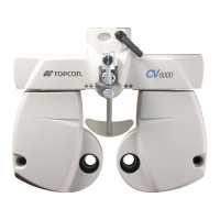
A shadowgram image is created by summing the 50 pixels under RPE
longitudinally on the 3D tomogram data, and is displayed as a B/W
image (see right). The fundus features (for example, blood vessel pat-
tern) are visible in the shadowgram image.
This software performs "Pin-point Registration™" by using the shadow-
gram data.
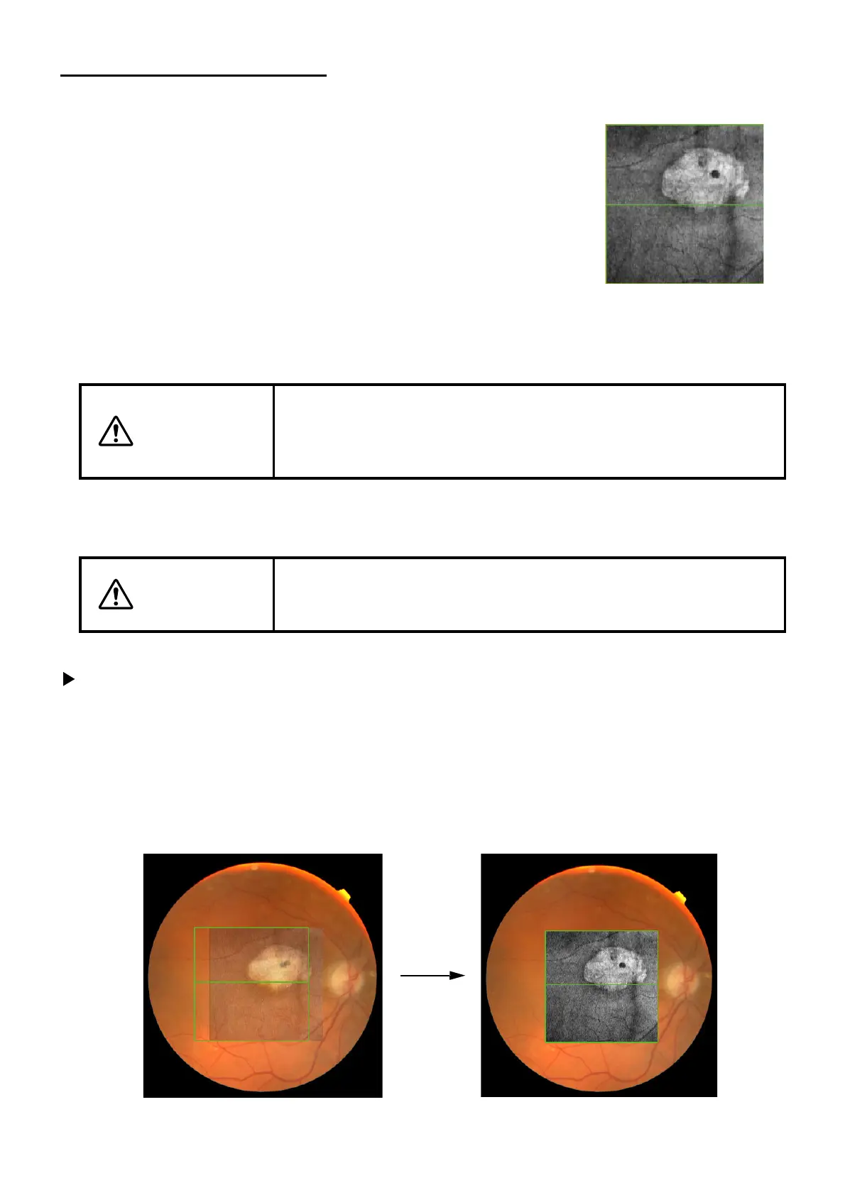
3.9.2. Automatic Positioning
After analysis, the shadowgram image and color fundus image are positioned automatically.
3.9.3. Manual Positioning
To Perform a Manual Positioning:
1 Click Overlay Reposition.
2 Place the cursor on the image. While depressing the left mouse button, drag the image to the
desired location.
3 The shadowgram image will become transparent to allow the user to move and align it to the
appropriate position of the color fundus image.
CAUTION
As the result of automatic positioning, the fundus image is sometimes
deformed to the oval shape on the fundus/anterior segment image dis-
play area (A-3). This is the result of the positioning process and there is
no problem.
CAUTION
After analysis, the images are automatically positioned. If sufficient data
required for overlapping are not provided, automatic positioning may not
be done correctly.