Setting 2: DC Injection Braking to Stop
When the Run command is removed, the drive
will baseblock (turn off its output) for the minimum baseblock time (L2-03).
Once the minimum baseblock time has expired, the drive will brake the motor by injecting DC current into the motor
windings. The stopping time will be reduced as compared to coast to stop. The level of DC Injection current is set by
parameter b2-02 (default = 50%).
Note: This function is not available when using PM Open Loop Vector.
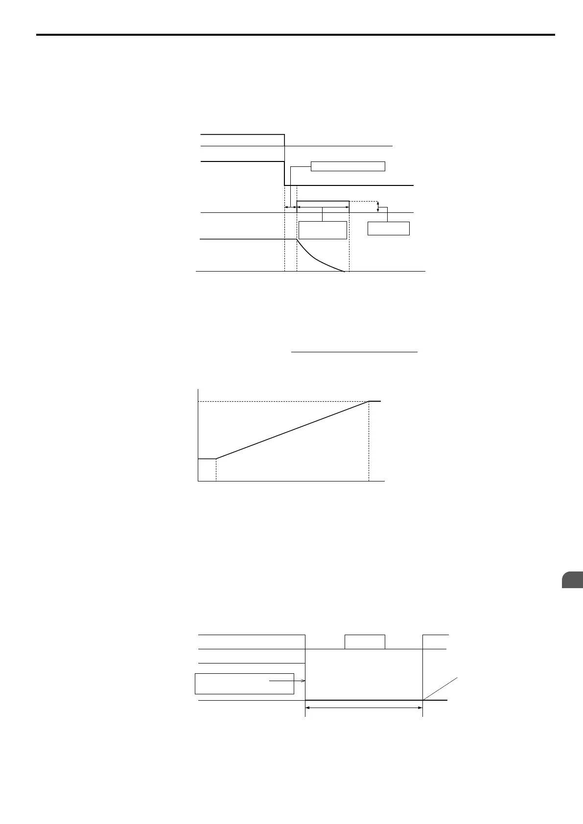
Run Command
Output Frequency
ON OFF
DC Injection Braking
Time at Stop
(b2-04)*
Minimum Baseblock Time (
L2-03)
DC Braking
Current (b2-02)
DC Injection Braking
Motor Speed
Figure 5.6 DC Injection Braking to Stop
The time for DC Injection Braking is determined by the value set to b2-04 and by the output frequency at the time the Run
command is removed. It can be calculated by:
=
DC Injection brake time
b2-04 • 10 • Output frequency
Max. output frequency (E1-04)
Output frequency when
Stop command was entered
100%
(Maximum output
frequency)
10%
DC Injection braking time
b2-04×10
b2-04
Figure 5.7 DC Injection Braking Time Depending on Output Frequency
Note: If
an
overcurrent
(oC)
fault
occurs
during
DC
Injection Braking to stop, lengthen the minimum baseblock time (L2-03) until the fault
no longer occurs.
Setting 3: Coast to Stop with Timer
When the Run command is removed, the drive will turn off its output and the motor will coast to stop. If a Run command
is input before the operation wait time t expires, the drive will not rotate the motor and the Run command will need to be
cycled before operation can occur.
Operation Wait Time t
Run Command
Output Frequency
ON ON ONOFF OFF
Drive output voltage
interrupted
Figure 5.8 Coast to Stop with Timer
5.2 b: Application
YASKAWA ELECTRIC SIEP C710606 16C YASKAWA AC Drive – V1000 Technical Manual
121
5
Parameter Details

 Loading...


