• Radiated Noise: Electromagnetic waves radiated from the drive and cables create noise throughout the radio bandwidth
that can affect devices.
• Induced Noise: Noise generated by electromagnetic induction can
affect the signal line and may cause the controller to
malfunction.
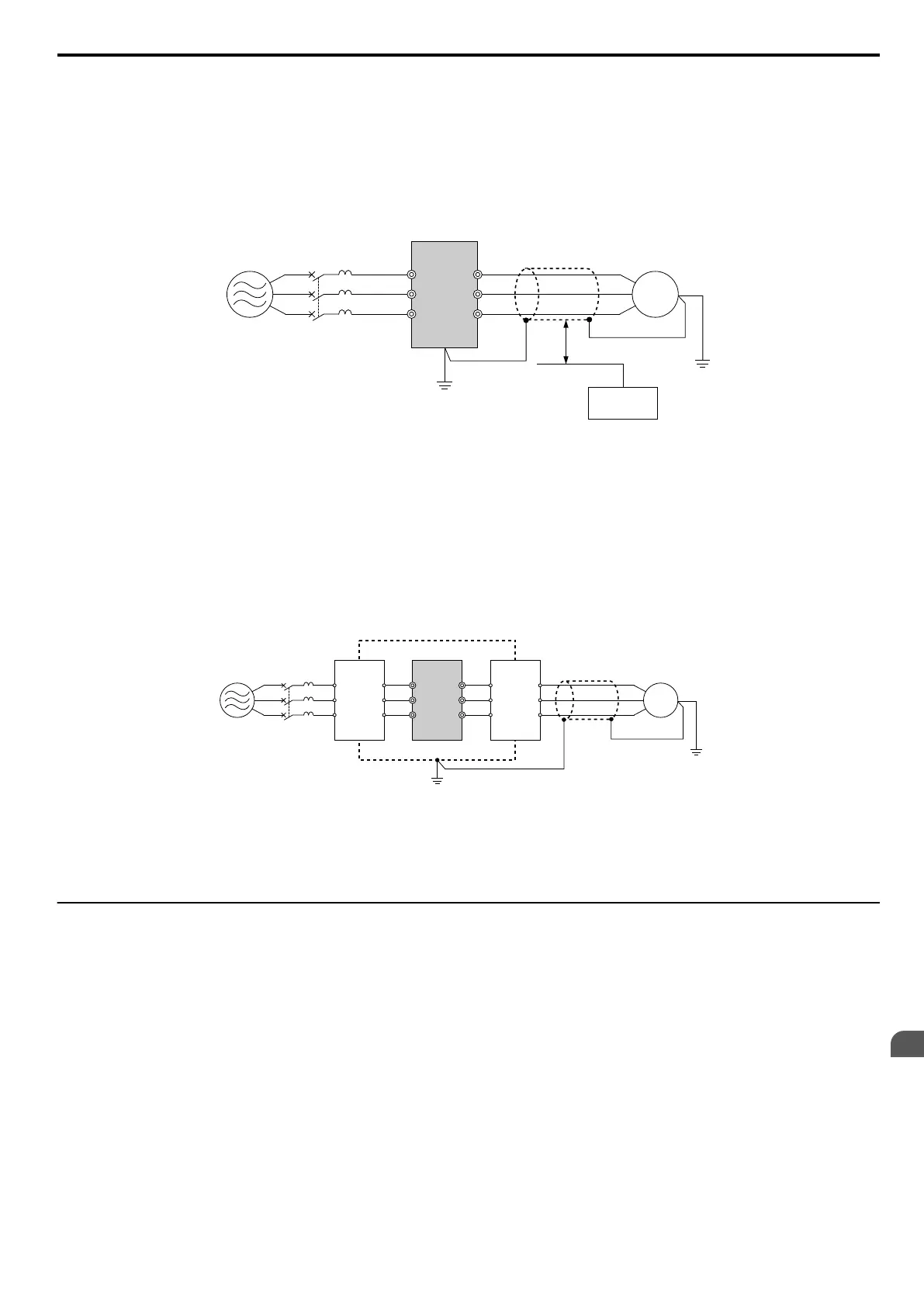
Preventing Induced Noise
Use a noise filter on the output side or use shielded cables. Lay the cables at least 30 cm away from the signal line to
prevent induced noise.
B
A
C
F
G
D
E
R/L1
MCCB
S/L2
T/L3
U/T1
V/T2
W/T3
A – Power supply
B – Drive
C – Shielded motor cable
D – Motor
E – Separate at least 30 cm
F – Controller
G – Signal line
Figure 8.8 Preventing Induced Noise
Reducing Radiated/Radio Frequency Noise
The drive, input lines, and output lines generate radio frequency noise. Use noise filters on input and output sides and
install the drive in a metal enclosure panel to reduce radio frequency noise.
Note: The cable running between the drive and motor should be as short as possible.
C ED
B
F
A
R/L1
MCCB
S/L2
T/L3
U/T1
V/T2
W/T3
G
A – Metal enclosure
B – Power supply
C – Noise filter
D – Drive
E – Noise filter
F – Shielded motor cable
G – Motor
Figure 8.9 Reducing Radio Frequency Noise
u
EMC Filter Installation
This drive is tested according to European standards
IEC/EN 61800-5-1 and it complies with the EMC guidelines. Refer
to EMC Filter Installation on page 436 for details about EMC filter selection and installation.
8.4 Installing Peripheral Devices
YASKAWA ELECTRIC SIEP C710606 16C YASKAWA AC Drive – V1000 Technical Manual
311
8
Peripheral Devices &
Options

 Loading...


