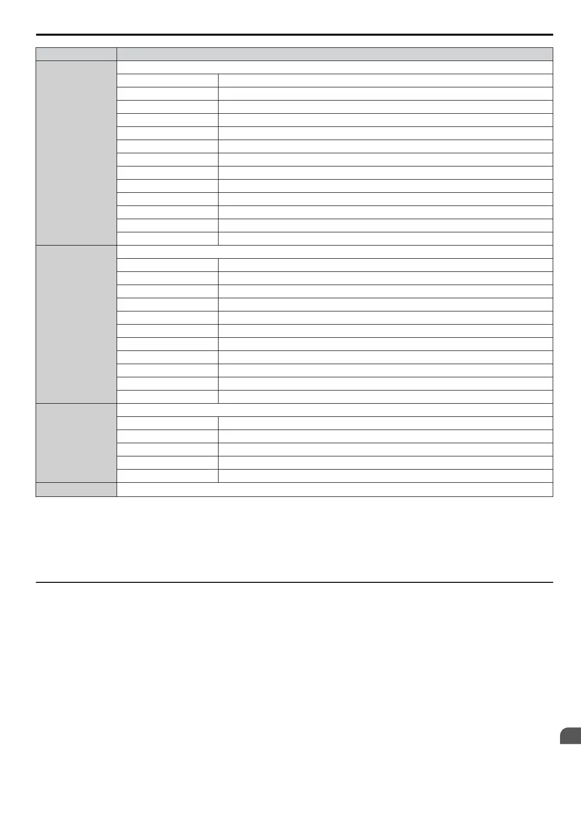
Register No. Contents
00D0H
CPF Contents 1
bit 0 to 1 Reserved
bit 2 A/D Conversion Error (CPF02)
bit 3 PWM Data Fault (CPF03)
bit 4 to 5 Reserved
bit 6 Drive specification mismatch during Terminal Board or Control Board replacement (CPF06)
bit 7 Terminal Board Communications Fault (CPF07)
bit 8 EEPROM Serial Communications Fault (CPF08)
bit 9 to A Reserved
bit B RAM Fault (CPF11)
bit C FLASH Memory Fault (CPF12)
bit D Watchdog Circuit Exception (CPF13)
bit E Control Circuit Fault (CPF14)
bit F Reserved
00D1H
CPF Contents 2
bit 0 Clock Fault (CPF16)
bit 1 Timing Fault (CPF17)
bit 2 Control Circuit Fault (CPF18)
bit 3 Control Circuit Fault (CPF19)
bit 4 Hardware fault at power up (CPF20)
bit 5 Hardware fault at communication start up (CPF21)
bit 6 A/D Conversion Fault (CPF22)
bit 7 PWM Feedback Fault (CPF23)
bit 8 Drive capacity signal fault (CPF24)
bit 9 Terminal board is not properly connected (CPF25)
bit A to F Reserved
00D8H
Option Card Fault Contents
bit 0 Option Compatibility Error (oFA00)
bit 1 Option not properly connected (oFA01)
bit 3 Option Self-diagnostics Error (oFA03)
bit 4 Option Flash Write Mode Error (oFA04)
bit 5 to F Reserved
00FBH
Output Current
<2>
<1> Units are determined by parameter o1-03.
<2> Display is in the following units: BA0001 to BA0018, 2A0001 to 2A0040, and 4A0001 to 4A0023: 0.01 A units.
2A0056 to 2A0069, 4A0031 to 4A0038: 0.1 A units.
<3> The communication error log is stored until the fault is reset.
<4> Depending on the motor used the correct motor pole number must be set to parameter E2-04, E4-04 or E5-05.
<5> Available in drive software versions PRG: 1011 and later.
u
Broadcast Messages
Data can be written from the master to all slave devices at the same time.
The slave address in a broadcast command message must be set to 00H. All slaves will receive the message, but will not
respond.
C.10 MEMOBUS/Modbus Data Table
YASKAWA ELECTRIC SIEP C710606 16C YASKAWA AC Drive – V1000 Technical Manual
425
C
MEMOBUS/Modbus
Communications

 Loading...


