Setting 100 to 192: Reverse Switching for Functions 0 to 92
These settings reverse the switching status of the specified function. Set as 1oo, where the last two digits specify the
setting number of the function to be reversed.
Examples:
• To reverse the output for “8: During Baseblock”, set “108”.
• To reverse the output for “4A: During KEB” set “14A” .
n
H2-06: Watt Hour Output Unit Selection
When one of the multi-function terminals
is set to output the number of watt hours (H2-01/02/03 = 39), parameter H2-06
determines the units for the output signal.
The output is intended to drive a watt hour meter or a PLC input by a 200 ms pulse signal. A pulse is output according to
the kWh unit selected in H2-06.
No. Parameter Name Setting Range Default
H2-06 Watt Hour Output Unit Selection
0: 0.1 kWh units
1: 1 kWh units
2: 10 kWh units
3: 100 kWh units
4: 1000 kWh units
0
u
H3: Multi-Function Analog Input Terminals
The drive is equipped with 2 multi-function analog input terminals, A1 and A2. The user can assign functions to these
terminals by setting parameters H3-02 and H3-10 between 0 and 31.
n
H3-01: Terminal A1 Signal Level Selection
Selects the input signal level for analog input A1.
No. Name Setting Range Default
H3-01 Terminal A1 Signal Level Selection 0 to 1 0
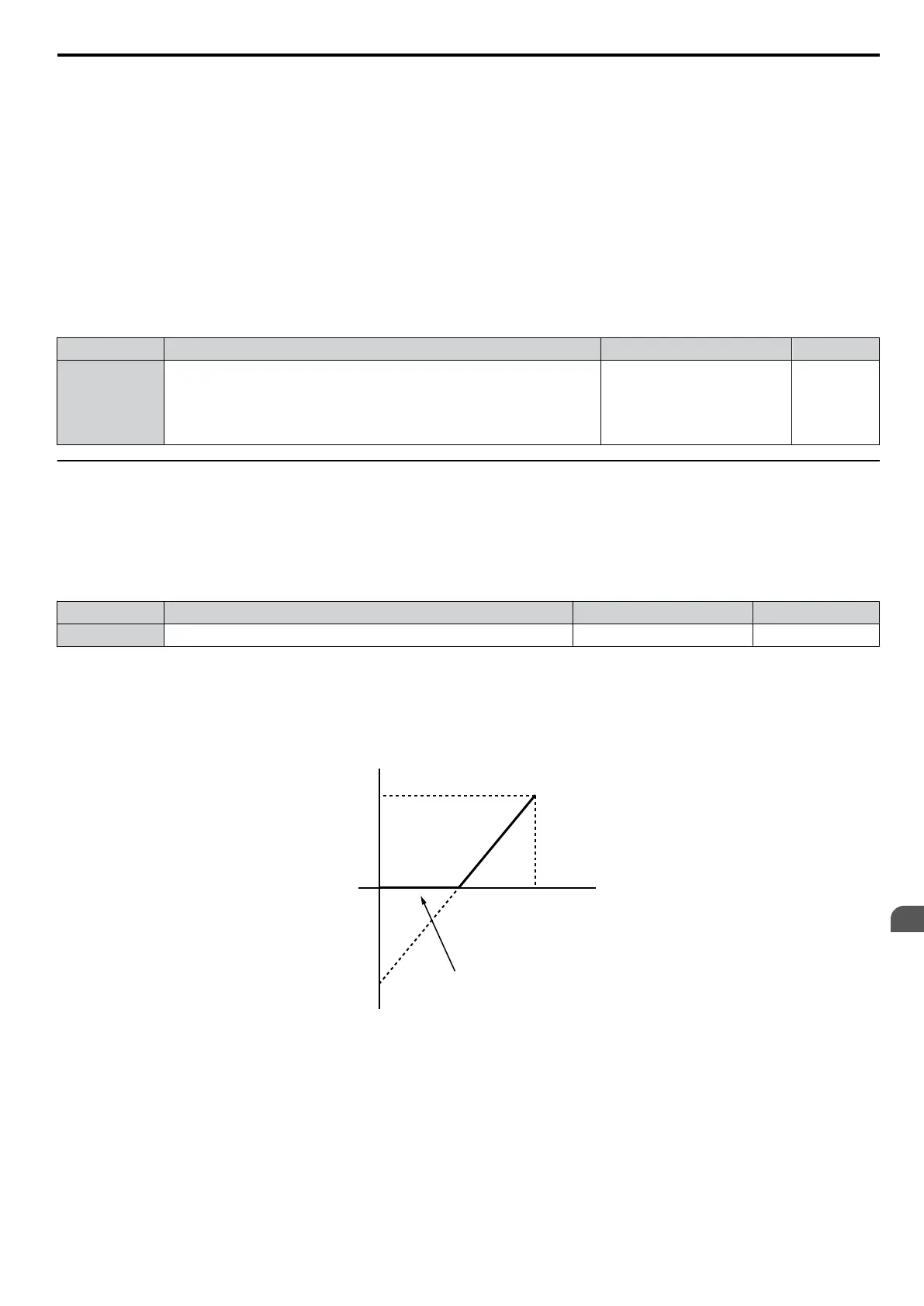
Setting 0: 0 to 10 Vdc with Limit
The input level is 0 to 10 Vdc. Negative input values will be limited to 0.
Example: Terminal A1 is set to supply the frequency reference, and the bias (H3-04) is set to -100%. The frequency
reference can be set from 0 to 100% with an analog input of 5 to 10 V. The frequency reference will be zero when the
analog input is between 0 and 5 V.
0
10 V
100%
-100%
Analog input
voltage
Analog input
value
Negative input is limited to 0
Figure 5.67 Analog Input with Limit (Bias Setting -100%)
Setting 1: 0 to 10 Vdc without Limit
The input level is 0 to 10 Vdc. Negative input values will be accepted.
Example: Terminal A1 is set to supply the frequency reference, and the bias (H3-04) is set to -100%. The frequency
reference can be set from 0 to 100%
with an analog input of 5 to 10 V. With an input of 0 to 5 V, the frequency reference
can be set from -100% to 0%. The drive reverses the motor rotation with negative input.
5.7 H: Terminal Functions
YASKAWA ELECTRIC SIEP C710606 16C YASKAWA AC Drive – V1000 Technical Manual
195
5
Parameter Details

 Loading...


