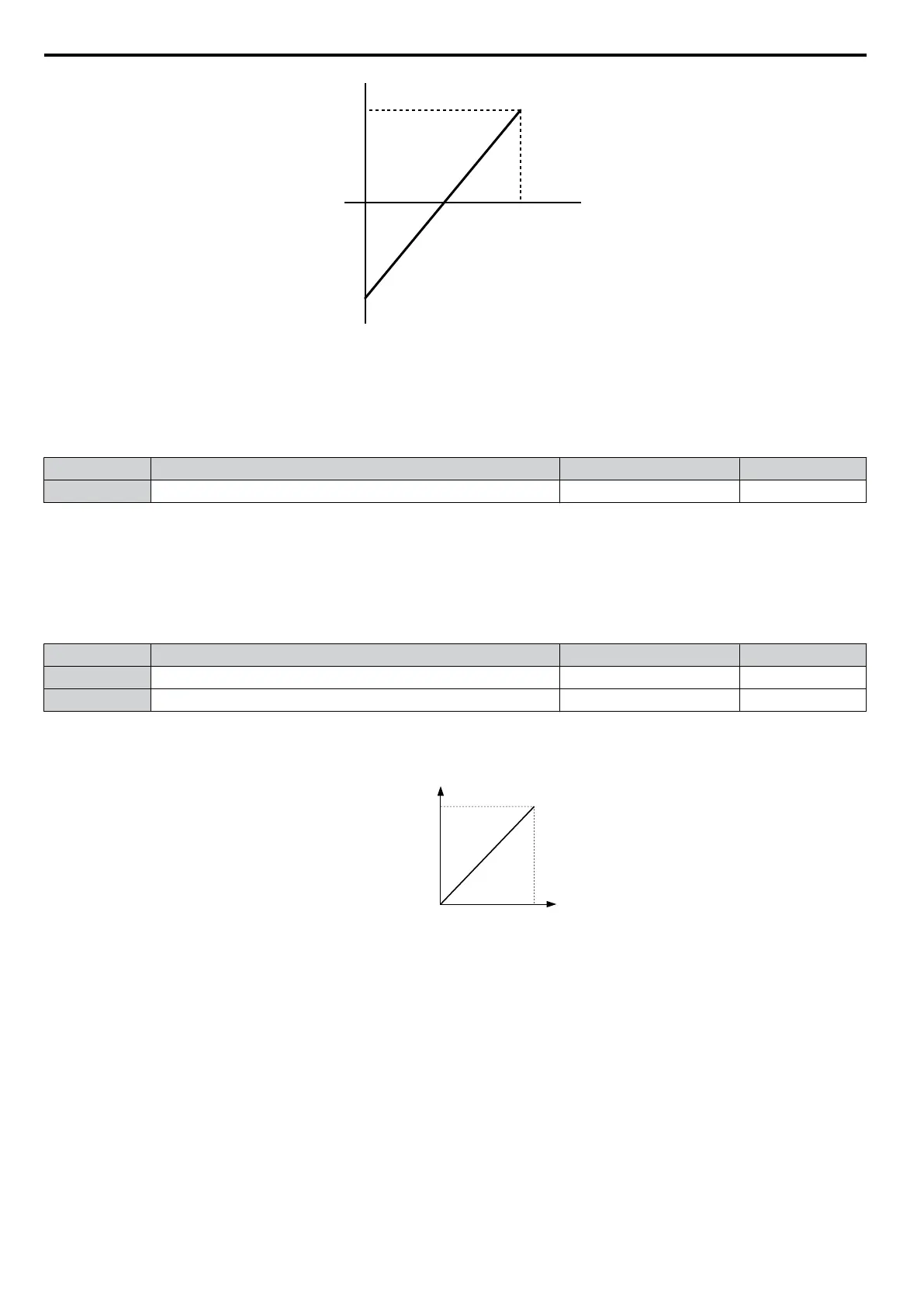
0V
10 V
100%
-100%
Analog input
voltage
Analog input
value
Figure 5.68 Analog Input without Limit (Bias Setting -100%)
n
H3-02: Terminal A1 Function Selection
Determines the function assigned to analog input terminal A1. Refer to Multi-Function Analog Input Terminal
Settings on page 198 for a list of functions and descriptions.
No. Name Setting Range Default
H3-02 Terminal A1 Function Selection 0 to 31 0
Note: If not using an input terminal or if using it in the through-mode, be sure to set that terminal to “F”.
n
H3-03/H3-04: Terminal A1 Gain/Bias Setting
Parameter H3-03 sets the level of the selected input value that is equal to 10 Vdc input at terminal A1 (Gain).
Parameter H3-04 sets the level of the selected input value that is equal to 0 V input at terminal A1.
Both can be used to adjust the analog input A1 characteristics.
No. Name Setting Range Default
H3-03 Terminal A1 Gain Setting -999.9 to 999.9% 100.0%
H3-04 Terminal A1 Bias Setting -999.9 to 999.9% 0.0%
Default Settings
Using the factory default settings for the analog
input’s function, gain, and bias, the 0 to 10 Vdc signal at the analog input
will yield a 0 to 100% frequency reference span.
0 V 10 V
Gain = 100 %
Frequency
reference
Bias = 0 %
Figure 5.69 Analog Input A1 Default Characteristics
Setting Examples
• Gain H3-03 = 200%, A1 as frequency reference input:
An input 10 Vdc will be equivalent to a 200% frequency reference and 5 Vdc will be equivalent to a 100% frequency
reference. Since the drive output is limited
by the maximum frequency parameter (E1-04), the frequency reference will
be equal to E1-04 above 5 Vdc.
5.7 H: Terminal Functions
196
YASKAWA ELECTRIC SIEP C710606 16C YASKAWA AC Drive – V1000 Technical Manual

 Loading...


