<3> Range upper limit is dependent on parameters E1-04, Maximum Output Frequency, and d2-01, Frequency Reference Upper Limit.
<4> Default setting is determined by the drive software version.
PRG: 1016 and later: 100.00%
PRG: 1015 and earlier: 0.00 %
u
E: Motor Parameters
No. Name Description Range Def.
Control
Mode
Addr. Hex Pg.
V/f
O
LV
PM
E1: V/f Pattern Characteristics
Use E1 parameters to set V/f characteristics for the motor.
E1-01
<1>
Input Voltage
Setting
This parameter must be set to the power supply voltage. It
sets the maximum and base voltage used by preset V/f
patterns
(E1-03 = 0 to E) and adjusts levels used by certain
functions.
WARNING! Electrical Shock Hazard. Drive input
voltage (not motor voltage) must be set in E1-01 for the
protective features of the drive to function properly. failure
to do so may result in equipment damage and/or death or
personal injury.
155 to 255 200 V S S S 300 162
E1-03
<2>
V/f Pattern
Selection
Selects a preset V/f pattern.
0: 50 Hz Constant torque 1
1: 60 Hz Constant torque 2
2: 60 Hz Constant torque 3 (50 Hz base)
3: 72 Hz Constant torque 4 (60 Hz base)
4: 50 Hz Variable torque 1
5: 50 Hz Variable torque 2
6: 60 Hz Variable torque 3
7: 60 Hz Variable torque 4
8: 50 Hz High starting torque 1
9: 50 Hz High starting torque 2
A: 60 Hz High starting torque 3
B: 60 Hz High starting torque 4
C: 90 Hz (60 Hz base)
D: 120 Hz (60 Hz base)
E: 180 Hz (60 Hz base)
F: Custom V/f. E1-04 through E1-13 settings define the
V/f pattern
0 to F F A A − 302 162
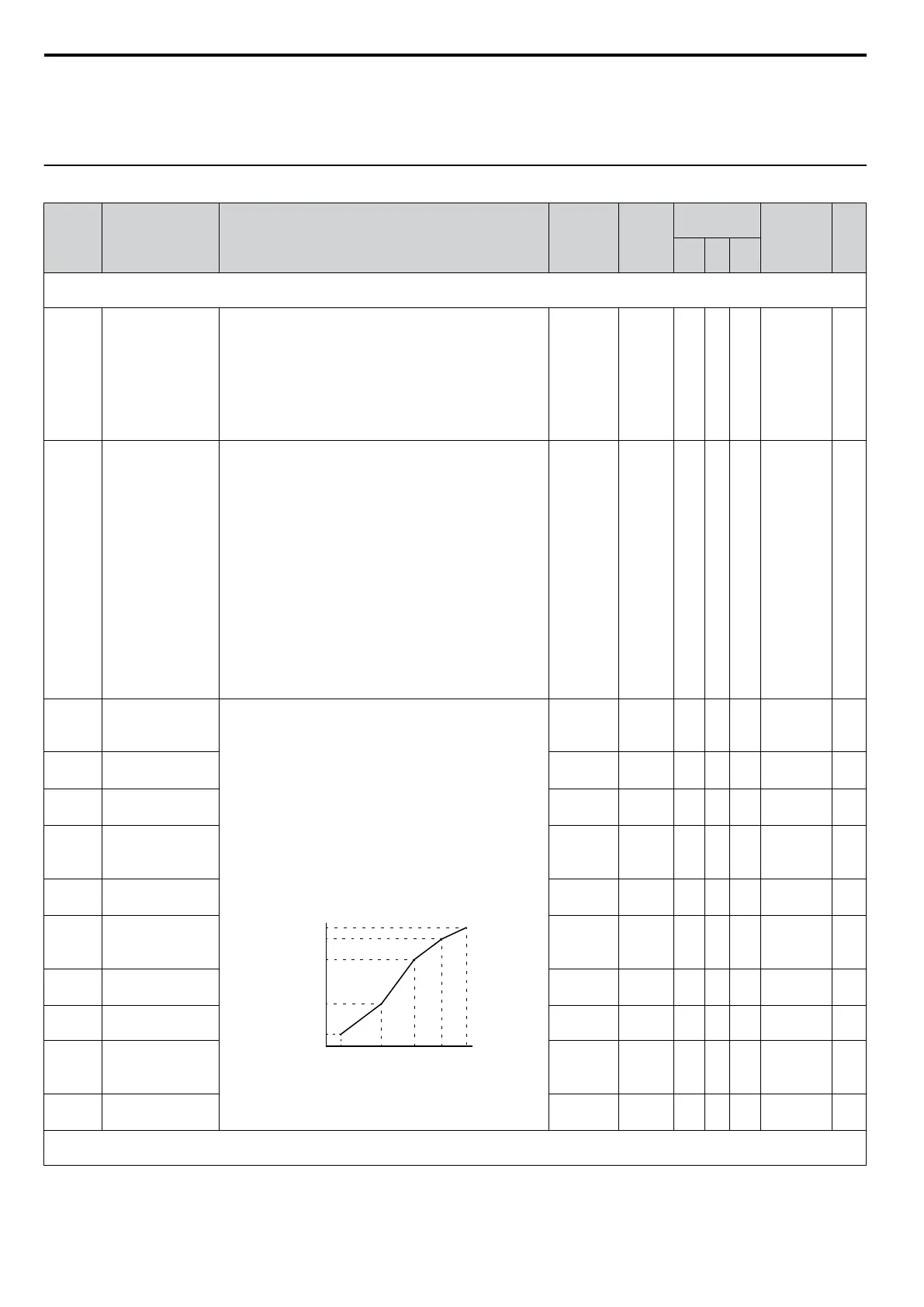
E1-04
Maximum Output
Frequency
E1-04 and E1-06 to E1-13 can only be changed when
E1-03 is set to F. To set linear V/f characteristics, set the
same values for E1-07 and E1-09. In this case, the setting
for E1-08 will be disregarded.
When E1-13 = 0.0 V, then the drive uses the value set to
E1-05 to control the voltage level.
Ensure that the five frequencies are set according to these
rules to prevent triggering an oPE10 fault:
E1-09 ≤ E1-07 < E1-06
≤ E1-11 ≤ E1-04
Note: Setting E1-11 to 0 disables both E1-11 and E1-12,
and the above conditions do not apply.
E1-09 E1-07 E1-06 E1-11 E1-04
E1-05
E1-12
E1-13
E1-08
E1-10
VACrms Out(V)
Frequency (Hz)
40.0 to
400.0
<3>
60 Hz
<4>
<19>
S S S 303 165
E1-05
<1>
Maximum Output
Voltage
0.0 to
255.0
200 V
<4>
S S S 304 165
E1-06 Base Frequency
0.0 to
E1-04
60 Hz
<4> <19>
S S S 305 165
E1-07
Middle Output
Frequency
0.0 to
E1-04
3.0 Hz
<3>
<19>
A A - 306 165
E1-08
<1>
Middle Output
Frequency Voltage
0.0 to
255.0
16.0 V
<5>
<6>
A A - 307 165
E1-09
Minimum Output
Frequency
0.0 to
E1-04
1.5 Hz
<5>
<4>
<19>
S S S 308 165
E1-10
<1>
Minimum Output
Frequency Voltage
0.0 to
255.0
9.0 V
<5> <6>
A A - 309 165
E1-11 Middle Output
Frequency 2
0.0 to
E1-04
0.0 Hz A A - 30A 165
E1-12
<1>
<7>
Middle Output
Frequency Voltage
2
0.0 to
255.0
0.0 V A A - 30B 165
E1-13
<1>
<9>
Base Voltage
0.0 to
255.0
0.0 V A S - 30C 165
E2: Motor Parameters
Use E2 parameters to set motor-related data.
B.2 Parameter Table
342
YASKAWA ELECTRIC SIEP C710606 16C YASKAWA AC Drive – V1000 Technical Manual

 Loading...


