n
d4-09: Frequency Reference Bias Lower Limit (Up/Down 2)
Parameter
d4-08 sets the lower limit of the
Up/Down 2 bias (monitor U6-20) and the value that can be saved in parameter
d4-06. Set this parameter to an appropriate value before using the Up/Down 2 function.
Note: When the frequency reference is set by the digital operator (b1-01 = 0) and d4-01 = 1, the bias value will be added to the frequency
reference if no Up/Down 2 command is received for 5 s, and will be reset to 0 afterwards. If the bias is increased using the Up 2
command, once it is added to the frequency reference the speed can not be reduced with a Down 2 command if the limit set in d4-09
is 0. In this case make sure to set a negative lower limit in d4-09 to allow speed reduction.
No. Parameter Name Setting Range Default
d4-09 Frequency Reference Bias Lower Limit -99.9 to 0.0% 0.0%
n
d4-10: Up/Down Frequency Reference Limit Selection
Selects how the lower frequency limit is set when the Up/Down function is used. Refer to Setting 10/11: Up/Down
Command
on page 179 for details on the Up/Down function in combination with frequency reference limits.
Setting 0: Lower Limit is Determined by d2-02 or Analog Input
The lower frequency reference limit is
determined by the higher value of both, parameter d2-02 or an analog input that is
programmed for “Frequency Bias” (H3-02/10 = 0).
Note:
If the external reference change over function (H1-oo = 2) used to switch between Up/Down function and analog input as reference
source, the analog value would become the lower reference limit when the Up/Down reference is active. Change d4-10 to 1 to make
the Up/Down function independent of the analog input value.
Setting 1: Lower Limit is Determined by Parameter d2-02
Only parameter d2-02 sets the lower frequency reference limit.
u
d7: Offset Frequencies
n
d7-01 to d7-03: Offset Frequency 1 to 3
Three
different offset values can be added to
the frequency reference. They can be selected using digital inputs programmed
for Offset frequency 1, 2 and 3 (H1-oo = 44, 45, 46). The selected offset values are added if two or all three inputs are
closed at the same time.
Note:
This function can be used to replace the “Trim Control” function (H1-oo = 1C/1D) of earlier Yaskawa drives.
No. Parameter Name Setting Range Default
d7-01 Offset Frequency 1 -100.0 to 100.0% 0%
d7-02 Offset Frequency 2 -100.0 to 100.0% 0%
d7-03 Offset Frequency 3 -100.0 to 100.0% 0%
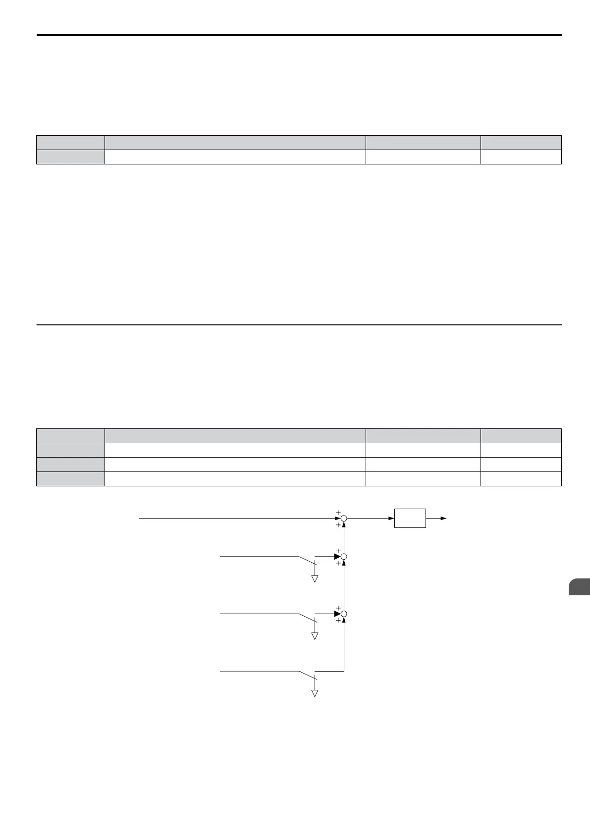
Figure 5.41 illustrates the Offset Frequency Function.
Frequency
reference
Offset Frequency 1 [d7-01]
(Signed)
Offset Frequency 2 [d7-02]
(Signed)
Offset Frequency 3 [d7-03]
(Signed)
Multi-function
input (44) = on
Multi-function
input (45) = on
Multi-function
input (46) = on
SFS
Frequency
reference after
soft starter
Figure 5.41 Offset Frequency Operation
5.4 d: Reference Settings
YASKAWA ELECTRIC SIEP C710606 16C YASKAWA AC Drive – V1000 Technical Manual
161
5
Parameter Details

 Loading...


