A.4 Drive Specifications
Note: 1. Perform rotational Auto-Tuning to obtain OLV performance specifications.
2. For optimum performance life of the drive, install the drive in an environment that meets the environmental conditions.
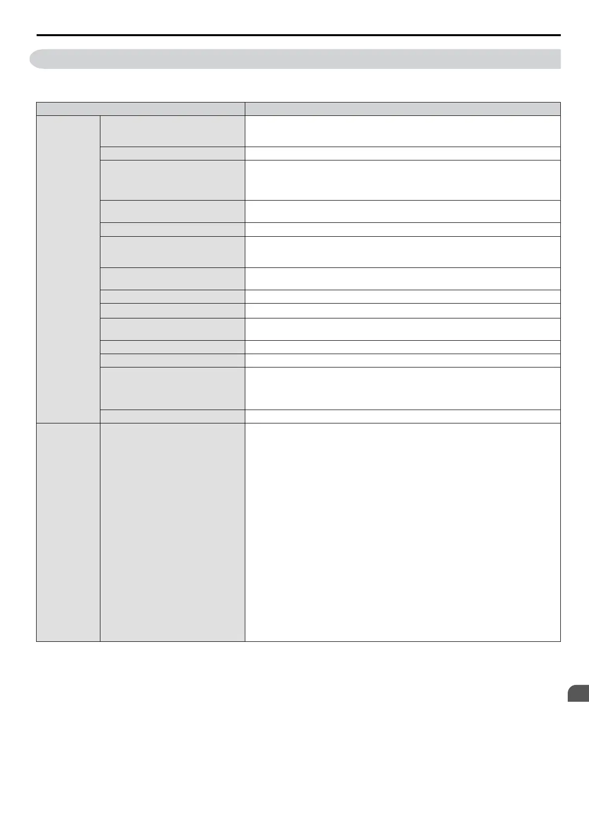
Item
Specification
Control
Character-
istics
Control Method
The following control methods are available:
Open Loop Vector Control (current vector), V/f Control, and PM Open Loop Vector (for
use with SPM and IPM)
Frequency Control Range
0.01 to 400 Hz
Frequency Accuracy
Digital input: within ±0.01% of the max output frequency
(-10 to +50 °C)
Analog input: within ±0.5% of the max output frequency
(25 °C ±10 °C)
Frequency Setting Resolution
Digital inputs: 0.01 Hz
Analog inputs: 1/1000 of maximum output frequency
Output Frequency Calculation Resolution
1/2
20
x Maximum output frequency (E1-04)
Frequency Setting Signal
Main frequency reference: 0 to +10 Vdc (20 kΩ), 4 to 20 mA (250 Ω), 0 to 20 mA
(250 Ω)
Main speed reference: Pulse Train Input (max 32 kHz)
Starting Torque
200%/0.5 Hz (OLV Control, HD rating, IM of 3.7 kW or smaller),
50%/6 Hz (OLV/PM Control)
Speed Control Range
1:100 (OLV Control), 1:40 (V/f Control), 1:10 (OLV/PM Control)
Speed Control Accuracy
±0.2% in Open Loop Vector Control
<1>
Speed Response
5 Hz (25 °C ±10 °C) in Open Loop Vector Control
(excludes temperature fluctuation when performing Rotational Auto-Tuning)
Torque Limit
Open Loop Vector Control only. Adjustable in 4 quadrants.
Accel/Decel Time
0.00 to 6000.0 s (allows four separate settings for accel and decel)
Braking Torque
Instantaneous Average Decel Torque
<2>
: 0.1/0.2 kW: over 150%, 0.4/0.75 kW: over
100%, 1.5 kW: over 50%, 2.2 kW and above: over 20%
Continuous Regen Torque: 20%,
125%
with a Braking Resistor Unit
<3>
: (10%
ED) 10 s with an internal braking resistor.
V/f Characteristics
Preset V/f patterns and user-set program available.
Control
Character-
istics
Functions
Momentary Power Loss Ride-Thru
Speed Search
Over/Undertorque Detection
Torque Limit, Multi-Step Speed (17 steps max)
Accel/Decel Time Switch
S-Curve Accel/Decel,
2-Wire/3-Wire Sequence
Rotational Auto-Tuning
Stationary Auto-Tuning of Line-to-Line Resistance
Dwell
Cooling Fan ON/OFF
Slip Compensation
Torque Compensation
Jump Frequencies (reference dead band)
Frequency Reference Upper/Lower Limit
DC Injection Braking (start and stop), High Slip Braking
PID Control (with Sleep Function)
Energy Saving
MEMOBUS/Modbus (RS-485/RS-422 Max 115.2 kbps)
Fault Reset
Parameter Copy
DriveWorksEZ
Fault Restart
Removable Terminals with Parameter Backup Function
A.4 Drive Specifications
YASKAWA ELECTRIC SIEP C710606 16C YASKAWA AC Drive – V1000 Technical Manual
323
A
Specifications

 Loading...


