L4-02
L4-01
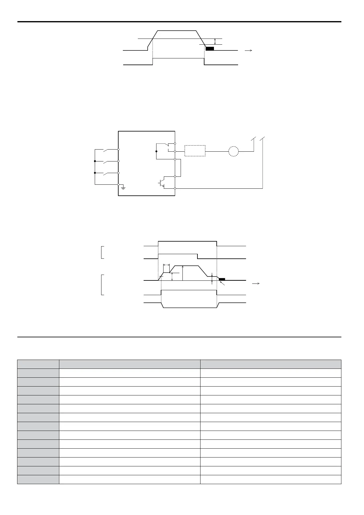
OFF
ON
time
output
frequency
Frequency
Dectection 2
Figure 4.10 Frequency Detection 2
The braking sequence should be designed as follows:
• A normally open signal (N.O.) should be used to control the brake so that it is released when terminal P2-PC closes.
• When a fault signal is output, the brake should close.
Note: The drawing below shows a control wiring example for the crane application preset:
Safety
Circuit
BR
Drive
(Forward)
24 V
Frequency Detect 2
UP
DOWN
High speed
Low speed
(Reverse)
S2
(Multi-step speed 2)
MA
MB
MC
P2
PC
S6
SC
Fault Contact
Holding brake
auxilary relay coil
S1
Figure 4.11 Brake Control Wiring
• When changing the speed using an analog signal, make sure that the source of the frequency reference is assigned to the
control circuit terminals (b1-01 = 1).
• A sequence to open and close the holding brake appears in the diagram below.
Time
UP
S1-SC
S6-SC
OFF
OFF
d1-03
d1-01 (Enabled when b1-01 = 0)
L4-01
b2-01
OFF
DC Injection braking
ON
ON
ON
P2-PC
Holding brake
Fast/Slow
Output frequency
0
Frequency Detection 2
(H2-03
=
05)
Closed Closed
Open
b6-02
b6-01
Input
Output
Figure 4.12 Holding Brake Time Chart
u
Setting 7: Traveling Application
Table 4.17 Traveling: Parameters and Settings
No. Parameter Name Default Setting
A1-02 Control Method Selection 0: V/f Control
b1-01 Frequency Reference Selection 1 0: Operator
C1-01 Acceleration Time 1 3.0 s
C1-02 Deceleration Time 1 3.0 s
C6-01 Drive Duty Selection 0: Heavy Duty
C6-02 Carrier Frequency Selection 2: 5 kHz
d1-01 Frequency Reference 1 6.0 Hz
d1-02 Frequency Reference 2 30.0 Hz
d1-03 Frequency Reference 3 60.0 Hz
H1-05 Multi-Function Digital Input Terminal S5 Function 3: Multi-Step Speed 1
H1-06 Multi-Function Digital Input Terminal S6 Function 4: Multi-Step Speed 2
H2-02 Terminals P1 Function Selection 37: During frequency output
L3-04 Stall Prevention Selection during Deceleration 0: Disabled
4.6 Application Selection
98
YASKAWA ELECTRIC SIEP C710606 16C YASKAWA AC Drive – V1000 Technical Manual

 Loading...


