8.3 Connecting Peripheral Devices
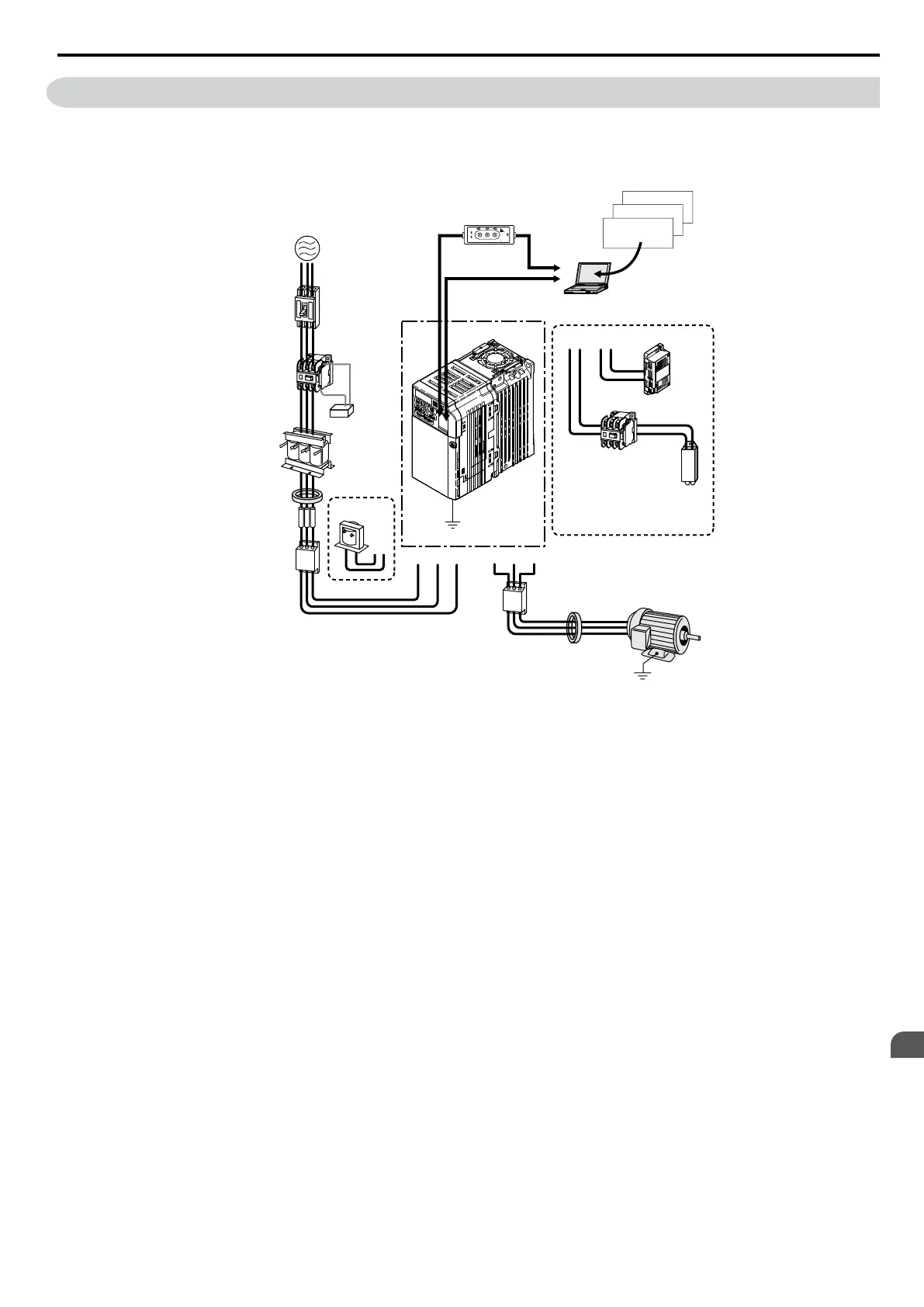
Figure 8.1 illustrates how the drive and motor connect together with various peripheral devices.
Refer to peripheral device option manual for detailed installation instructions.
Copy
Verify
Read
LOCK
YASKAWA
JVOP-181
USB Copy Unit
COM ERR
Ground
PC
Ground
Motor
Power
supply
U/T1 V/T2 W/T3R/L1 S/L2
+2+1
T/L3
B1
B2
24V
power supply
option
Line
breaker
(MCCB)
or
Leakage
breaker
Magnetic
contactor
(MC)
Surge
absorber
AC reactor
Zero phase
reactor
Fuse
DC Reactor
Braking
resistor
unit
Zero phase
reactor
Input Side
Noise Filter
Magnetic Contactor
(MC)
Output Side
Noise Filter
24V option
connector
Engineering software tools
DriveSelect
DriveWizard
DriveWorksEZ
Dedicated Cable
(RJ-45/D-sub adapter)
RJ-45 cable
Drive
USB Copy Unit
(RJ-45/USB adapter)
USB cable
<1>
Figure 8.1 Connecting Peripheral Devices
<1> NOTICE: Do
not connect the LAN port on a
PC and the comm. port of the drive. Failure to comply may damage the
drive and the PC.
Note: If the drive is set to trigger an output terminal when performing a fault restart (L5-02 = 1), the power supply will be shut off during
fault restart as the drive outputs a fault signal. Keep this in mind when designing a wiring sequence to interrupt the power to the drive.
The default setting for the drive is to not trigger an output terminal that indicates a fault restart is being performed (L5-02 = 0).
8.3 Connecting Peripheral Devices
YASKAWA ELECTRIC SIEP C710606 16C YASKAWA AC Drive – V1000 Technical Manual
307
8
Peripheral Devices &
Options

 Loading...


