u
Connecting a Noise Filter
n
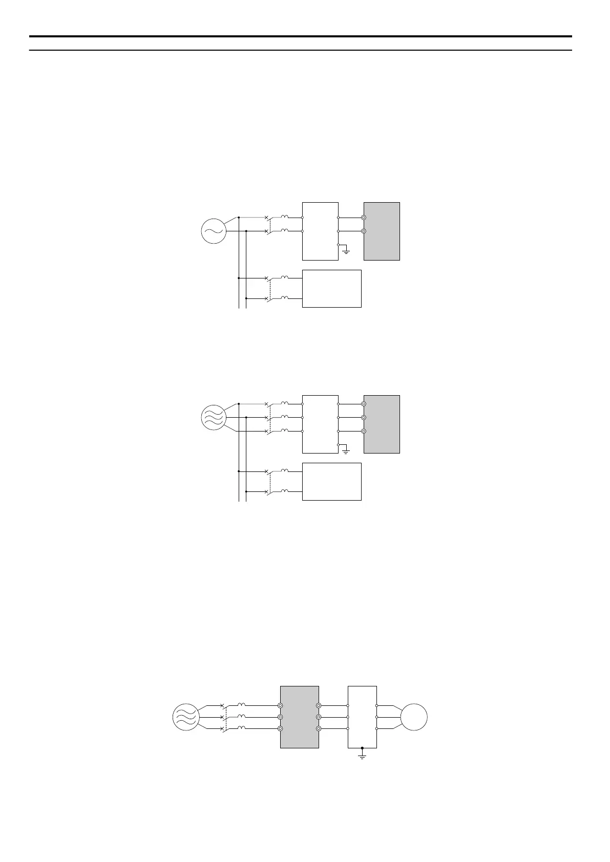
Input-Side Noise Filter
Drive outputs generate noise as a result of high-speed switching. This noise flows from inside the drive back toward the
power supply, possibly affecting other equipment. Installing a noise filter to the input side of the drive can reduce the
amount of noise flowing back into the power supply. This also prevents noise from entering the drive from the power
supply.
•
Use a noise filter specifically designed for AC drives.
• Install the noise filter as close as possible to the drive.
B C
D
A
R/L1
1
2
3
4
E
MCCB
MCCB
S/L2
A – Power supply
B – Input-side noise filter (Model:
LNFB-oo)
C – Drive
D – Other control device
Figure 8.5 Input-Side Noise Filter (Single-Phase 200 V)
C
D
A
B
R/L1
U
V
W
R
S
T
E
MCCB
MCCB
S/L2
T/L3
A – Power supply
B – Input-side noise filter (Model:
LNFD-oo)
C – Drive
D – Other control device
Figure 8.6 Input-Side Noise Filter (Three-Phase 200/400 V)
Refer to EMC Filter Installation
on
page
436
for
details
about
EMC filter selection and installation in order to make the
drive compliant with European standards IEC/EN 61800-3 and the EMC guidelines.
n
Output-Side Noise Filter
A noise filter on the output side of the drive reduces inductive noise and radiated noise. Figure 8.7 illustrates an example
of output-side noise filter wiring.
NOTICE: Do not connect phase-advancing capacitors or LC/RC noise filters to the output circuits. Improper application of noise filters
could result in damage to the drive.
CB
A
D
R/L1
MCCB
S/L2
T/L3
U/T1
V/T2
W/T3
1
2
3
4
5
6
A – Power supply
B – Drive
C – Output-side noise filter
D – Motor
Figure 8.7 Output-Side Noise Filter
8.4 Installing Peripheral Devices
310
YASKAWA ELECTRIC SIEP C710606 16C YASKAWA AC Drive – V1000 Technical Manual

 Loading...


