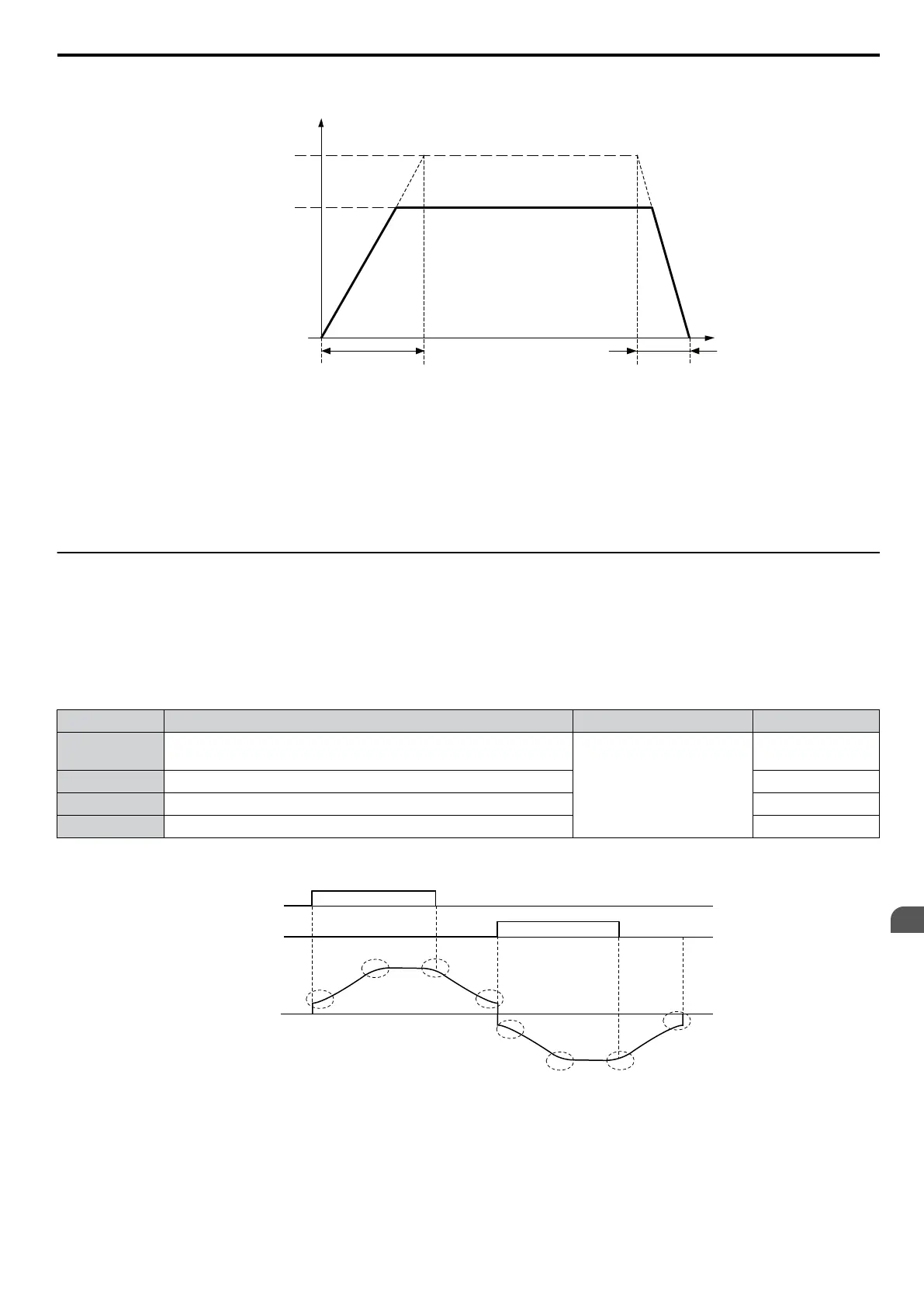
Time
C1-14 = 80 Hz
0
Output
frequency
Frequency
reference = 60 Hz
Accel Times 1 to 4
Decel Times 1 to 4
Figure 5.26 Accel/Decel Rate, Example 3 (C1-14 = 80 Hz, E1-04 = 60 Hz, Frequency Reference = 60 Hz)
Note:
1. The
accel/decel
times
shown
in Figure
5.24
to Figure 5.26 assume S-curve characteristic time during accel/decel at start and accel/
decel at stop of 0.00 s (parameters C2-01 to C2-04).
2. When Stall Prevention during acceleration is enabled (L3-01 ≠ 0), the accel time may take longer than the set value.
3. When Stall Prevention during deceleration is enabled (L3-04 ≠ 0), the decel time may take longer than the set value.
4. When performing Rotational Auto-Tuning for OLV Control (T1-01 = 0) and Rotational Auto-Tuning for V/f Control (T1-04 = 3),
the drive uses the maximum output frequency set in E1-04 to determine the base accel/decel rate, regardless of the C1-14 value.
u
C2: S-Curve Characteristics
Use S-curve characteristics to smooth acceleration and deceleration
and to minimize abrupt shock to the load. Set S-curve
characteristic time during acceleration/deceleration at start and acceleration/deceleration at stop. If a STo fault (Step Out
Detection) occurs when starting a PM motor, try increasing the value set to C2-01.
n
C2-01 to C2-04: S-Curve Characteristics
C2-01 through C2-04 set separate S-curves for each section of the acceleration or deceleration.
No. Parameter Name Setting Range Default
C2-01 S-Curve Characteristic at Accel Start
0.00 to 10.00 s
Determined by
A1-02
C2-02 S-Curve Characteristic at Accel End 0.20 s
C2-03 S-Curve Characteristic at Decel Start 0.20 s
C2-04 S-Curve Characteristic at Decel End 0.00 s
Figure 5.27 explains how S-curves are applied.
C2-02
C2-01
C2-03
C2-04
C2-02
C2-01
C2-03
C2-04
FWD run
REV run
Output
frequency
Figure 5.27 S-Curve Timing Diagram - FWD/REV Operation
Setting the S-curve will increase the acceleration and deceleration times.
Actual accel time = accel time setting + (C2-01 + C2-02)/2
Actual decel time = decel time setting + (C2-03 + C2-04)/2
5.3 C: Tuning
YASKAWA ELECTRIC SIEP C710606 16C YASKAWA AC Drive – V1000 Technical Manual
145
5
Parameter Details

 Loading...


