3.7 Control Circuit Wiring
NOTICE: Do not solder the ends of wire connections to the drive. Soldered wire connections can loosen over time. Improper wiring
practices could result in drive malfunction due to loose terminal connections.
+
-
Forward run/stop
Reverse run/stop
External fault
Fault reset
Multi-step
speed 2
Jog reference
V1000
Control circuit
S1
S2
S3
S4
S5
S6
S7
24 V
+
24 V 8 mA
Digital output
5 to 48 Vdc
2 to 50 mA
(default setting)
Digital output
ac, 10 mA to 1 A
30 Vdc, 10 mA to 1 A
(default setting)
Multi-step
speed 1
main/aux switch
Option card
connector
<1>
MA
MB
MC
Fault
DIP
switch S3
Digital inputs
(default setting)
Shield ground
terminal
P1
SC
P2
PC
RP
+V
A1
A2
AC
Pulse train input
(max. 32 kHz)
0 to +10 V (20 k
)
Setting power supply
+10.5 max. 20 mA
0 to +10 V (20 k
)
(0)4 to 20 mA (250
)
During Run
(photocoupler 1)
Frequency agree
(photocoupler 2)
Photocoupler
output common
Sink
Source
<2>
0 to +10 Vdc
(2 mA)
MP
AM
AC
2 k
Pulse train output
0 to 32 kHz
Analog monitor
output
Main speed
frequency
reference.
Multi-function
programmable
Comm.
connector
Safe Disable
Input
Safety switch
IG
R
+
R
-
S
+
S
-
AM
HC
H1
MEMOBUS/
Modbus comm.
RS-485/422
Termination
resistor
Monitor
output
Jumper
DIP
switch
S2
Cable shield ground
120
, 1/2 W
main circuit terminal
shielded line
twisted-pair shielded line
control terminal
250 V
0 V
V I
DIP switch S1
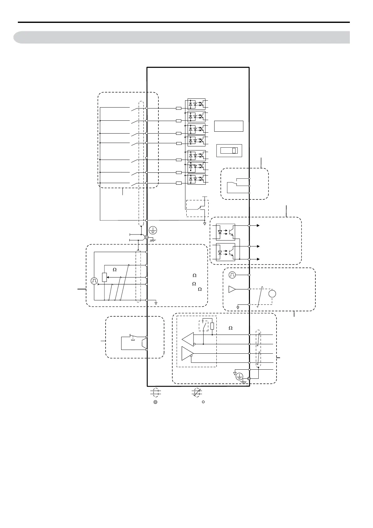
Figure 3.16 Control Circuit Connection Diagram
<1> Connected using sequence input signal (S1 to S7) from NPN transistor; Default: sink mode (0 V com)
<2> Use only the +24 V internal power
supply in sinking mode; the source mode requires an external power supply. Refer
to I/O Connections on page 67.
3.7 Control Circuit Wiring
62
YASKAWA ELECTRIC SIEP C710606 16C YASKAWA AC Drive – V1000 Technical Manual

 Loading...


