6.7 Auto-Tuning Fault Detection
Auto-Tuning faults are shown below. When the following faults are detected, the fault is displayed on the Digital Operator
and the motor coasts to a stop. No fault or alarm outputs will occur
u
Auto-Tuning Codes, Causes, and Possible Solutions
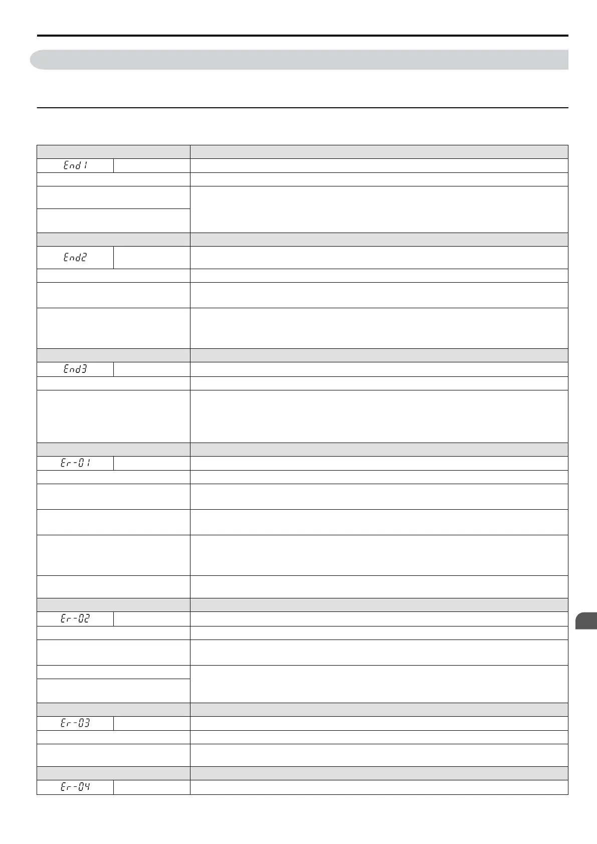
Table 6.12 Auto-Tuning Codes, Causes, and Possible Solutions
LED Operator Display Error Name
End1 Excessive V/f Setting. Displayed after Auto-Tuning is complete.
Cause Possible Solutions
The torque reference exceeded 20%
during Auto-Tuning.
• Before Auto-Tuning the drive, verify the information written on the motor nameplate and enter that
data to T1-03 through T1-05.
•
Enter proper information to parameters T1-03 to T1-05 and repeat Auto-Tuning.
• If possible, disconnect the motor from the load and perform Auto-Tuning.
The no-load current exceeded
80% of the
drive rated current during Auto-Tuning.
LED Operator Display Error Name
End2
Motor Iron-Core Saturation Coefficient. Detected only during Rotational Auto-Tuning and displayed
after Auto-Tuning is complete.
Cause Possible Solutions
Motor data entered during Auto-Tuning
was incorrect.
• Enter the correct data.
• Restart Auto-Tuning and enter the correct information.
Auto-Tuning calculated values outside
the parameter setting range, assigning the
iron-core saturation coefficient (E2-07,
E2-08) a temporary value.
• Check and correct faulty motor wiring.
• Disconnect the motor from machine and perform Rotational Auto-Tuning.
LED Operator Display Error Name
End3 Rated Current Setting Alarm (displayed after Auto-Tuning is complete)
Cause Possible Solutions
• The motor line-to-line resistance and
the motor-rated current are not
consistent with one another.
• The correct current rating printed on the
nameplate was not entered into T1-04.
• Check the setting of parameter
T1-04.
• Check the motor data and repeat Auto-Tuning.
LED Operator Display Error Name
Er-01 Motor Data Error
Cause Possible Solutions
Motor data entered during Auto-Tuning
was incorrect.
• Enter the correct data.
• Restart Auto-Tuning and enter the correct information.
Motor output and motor-rated current
settings (T1-02 and T1-04) do not match.
• Check the drive and motor capacities.
•
Correct the settings of parameters T1-02 and T1-04.
Motor output and no-load current settings
(T1-04 and E2-03) do not match. Data
required when Auto-Tuning for OLV
Control or Stationary Auto-Tuning.
• Check the motor-rated current and no-load current.
• Correct the settings of parameters T1-04 and E2-03.
Base frequency and base motor rotations
(T1-05 and T1-07) do not match.
Set T1-05 and T1-07 to the correct value.
LED Operator Display Error Name
Er-02 Minor Fault
Cause Possible Solutions
Motor data entered during Auto-Tuning
was incorrect.
• Enter the correct data.
•
Restart Auto-Tuning and enter the correct information.
The wiring is faulty. •
Check the wiring and correct defective connections.
•
Check around the machine.
•
Check the load.
Load is too heavy.
LED Operator Display Error Name
Er-03 STOP Button Input
Cause Possible Solutions
Auto-Tuning canceled by pressing STOP
button.
Auto-Tuning did not complete properly and will have to be performed again.
LED Operator Display Error Name
Er-04 Line-to-Line Resistance Error
6.7 Auto-Tuning Fault Detection
YASKAWA ELECTRIC SIEP C710606 16C YASKAWA AC Drive – V1000 Technical Manual
277
6
Troubleshooting

 Loading...


