8.2 Drive Options and Peripheral Devices
The following table of peripheral devices lists the names of the various devices/options available for Yaskawa drives.
Contact Yaskawa or your Yaskawa agent to order these peripheral devices.
• Peripheral Device Selection: Refer to Yaskawa catalog for selection and part numbers.
• Peripheral Device Installation: Refer to option manual for option installation instructions.
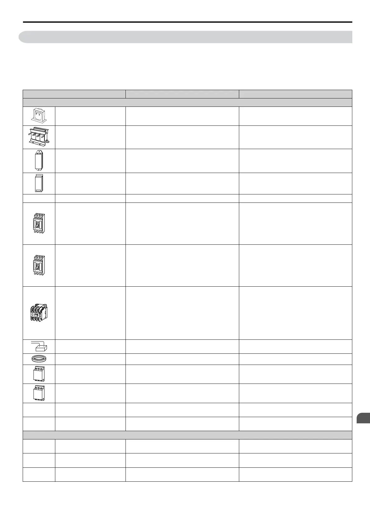
Table 8.1 Available Peripheral Devices
Option Model Number Description
Power Options
DC Reactor UZDA Series DC reactor to improve power factor
AC Reactor UZBA Series AC reactor to improve power factor
Braking Resistor ERF-150WJ Series 3% ED, 150 W braking resistor
Braking Resistor Unit LKEB Series Braking resistor
— Braking Chopper CDBR Series External braking transistor
Molded Case Circuit Breaker NF Series
Circuit breaker for short circuit or overload
protection
Note: Yaskawa recommends installing an MCCB
to the power supply side to protect drive wiring
and to prevent other damage in the event of
component failure. Install an MCCB if permitted
by the power system.
Earth Leakage Circuit Breaker
(ELCB)
NV, EG, or SG Series
Provides protection against potentially harmful
leakage currents
Note: Yaskawa recommends installing an ELCB
to the power supply side to protect drive wiring
and to prevent other damage in the event of
component failure. An MCCB can also be used
if
permitted by the power system.
Magnetic Contactor (Input) SC Series
Prevents potential damage to the braking resistor
and other internal circuitry by ensuring that power
to drive is completely shut off when necessary.
Install
an MCCB when using a braking resistor to
prevent the braking resistor from overheating.
Wire the MC so that it opens when a fault output
terminal is triggered to protect internal
components from sudden high levels of input
current.
Surge Absorber
200 V class: DCR2-oA
400 V class: RFN3AL-504KD
Suppresses surge voltage caused by switching
magnetic contactors
Zero Phase Reactor F6045GB Reduces electromagnetic noise
Input Noise Filter LNFB, LNFD Series
Reduces electromagnetic noise flowing back from
the drive into power supply
Output Noise Filter LF-310 Series
Reduces electromagnetic noise generated by the
drive output
— Isolator
DGPooo
Isolates the drive control I/Os for improved noise
resistance
—
Momentary Power Loss
Recovery Unit
200V class: P0010
400V class: P0020
—
Reference Setting / Monitor Options
— Frequency Meter / Ammeter DCF-6A
External meter for displaying the output frequency
or current using an analog signal from the drive
—
Frequency Meter Scaling
Resistor (20 kΩ)
RV30YN20S20kΩ
External potentiometer for adjusting the frequency
meter scaling
— Voltmeter SCF-12NH
External meter for displaying the output voltage
using an analog signal from the drive
8.2 Drive Options and Peripheral Devices
YASKAWA ELECTRIC SIEP C710606 16C YASKAWA AC Drive – V1000 Technical Manual
305
8
Peripheral Devices &
Options

 Loading...


