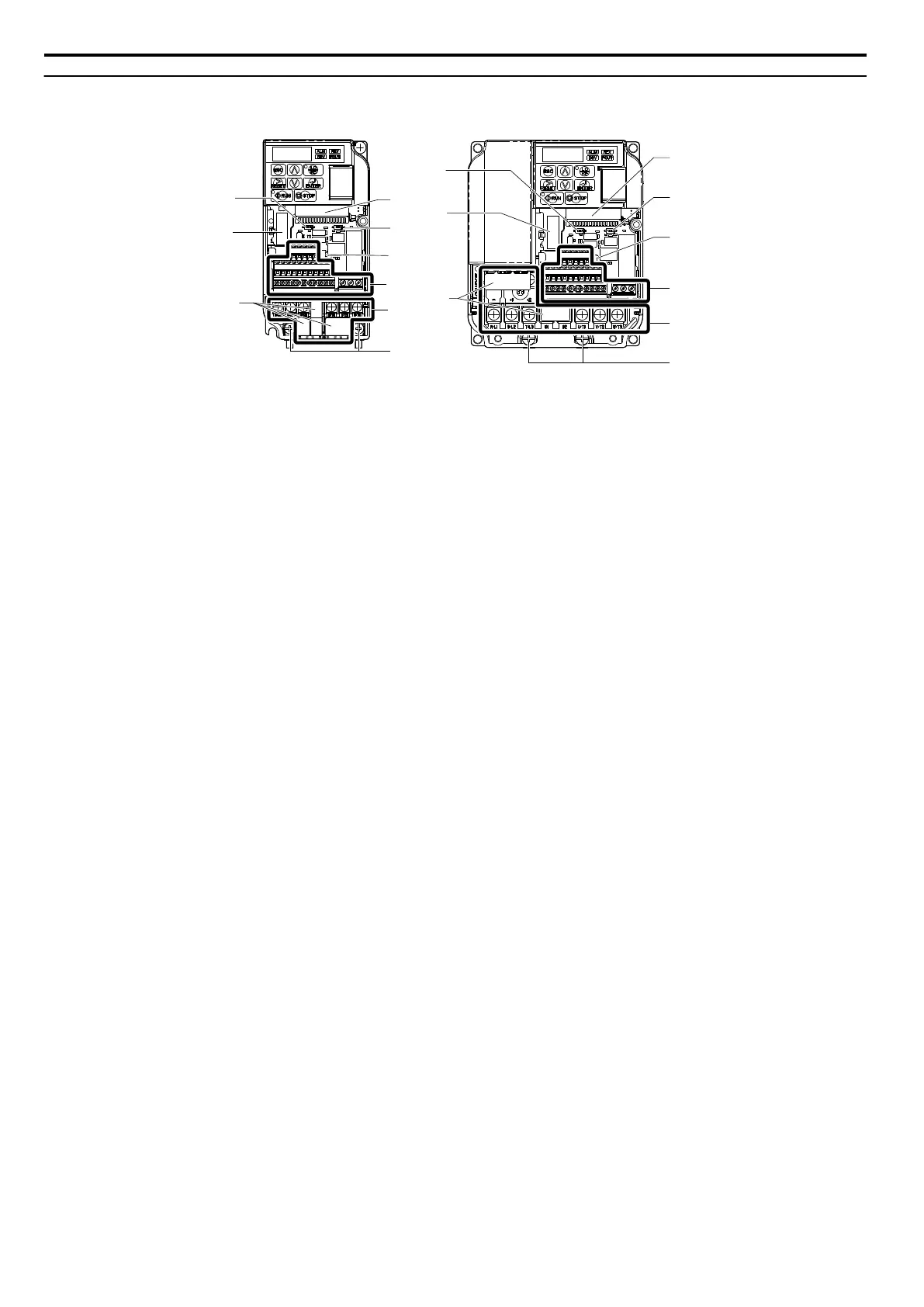
EasyManuals Logo

YASKAWA V1000 Technical Manual

YASKAWA V1000
480 pages
To Next Page IconTo Next Page
To Previous Page IconTo Previous Page
Page #34 background imageLoading...
Page #34 background image
u
Front Views
I
H
F
A
B
C
D
E
G
I
A
B
C
D
E
F
G
H
2A0006B 2A0012B
A Terminal board connector
B DIP switch S1 Refer to DIP Switch
S1 Analog Input Signal Selection
on page 69
C DIP switch S3 Refer to Sinking/
Sourcing Mode Switch on page
67
D Control circuit terminal Refer to
Control Circuit Wiring on page
62
E Main circuit terminal Refer to
Wiring the Main Circuit Terminal
on page 61
F Ground terminal
G Terminal cover
H Option card connector Refer to
Connecting the Option Card on
page 315
I DIP switch S2 Refer to MEMOBUS/
Modbus Termination on page
70
Figure 1.6 Front Views of Drives
1.4 Component Names
34
YASKAWA ELECTRIC SIEP C710606 16C YASKAWA AC Drive – V1000 Technical Manual

Table of Contents

Other manuals for YASKAWA V1000

Questions and Answers:

Question and Answer IconNeed help?

Do you have a question about the YASKAWA V1000 and is the answer not in the manual?

YASKAWA V1000 Specifications

General IconGeneral
Input Voltage3-Phase 200-240VAC, 3-Phase 380-480VAC
Output Voltage3-Phase 200-240VAC, 3-Phase 380-480VAC
Output Frequency0-400 Hz
Control MethodV/f control
Overload Capacity150% for 60 seconds
Protection FunctionsOvercurrent, Overvoltage, Undervoltage, Overheating, Short Circuit, Ground Fault
Communication OptionsModbus RTU
Ambient Temperature-10 to +50°C (14 to 122°F)
Storage Temperature-20°C to +65°C (-4°F to 149°F)
Humidity95% (non-condensing)
Cooling MethodForced Air Cooling
EnclosureIP20

Related product manuals