C.4 Connecting to a Network
This section explains the connection of a drive to a MEMOBUS/Modbus network and the network termination.
u
Network Cable Connection
Follow the instructions below to connect the drive to a MEMOBUS/Modbus network.
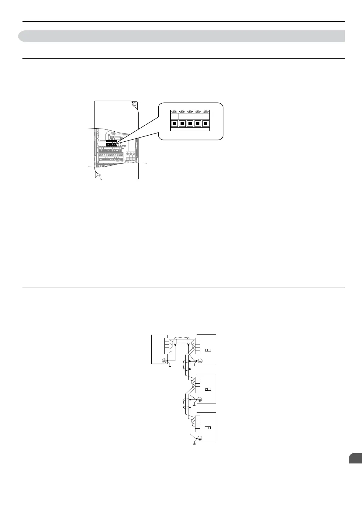
1.
With the power shut off, connect the communications
cable to the drive and the master. Use the terminals shown
in the figure below for network cable connections.
S1 S2 S3 S4 S5 S6 S7 HC SC H1 RP
R+ R
-
S+ S
-
IG
P1 P2 PC A1 A2 +V AC AM AC MP
MCMBMA
R+ R- S+ S- IG
R+ Receive (+)
R- Receive (-)
S+ Send (+)
S- Send (-)
IG Shield Ground
Figure C.2 Serial Communications Cable Connection Terminals
Note: Separate the communications cables from the main circuit cables and other wiring and power cables. Use shielded cables
for the communications cables, and properly shielded clamps to prevent problems with noise. When using RS-485
communications, connect S+ to R+, and S- to R- as shown in the diagram below.
2.
Check or set the terminating resistance at all slaves. Use the description in Network Termination for slaves that
are V1000 drives.
3.
Switch the power on.
4.
Set the parameters needed for serial communications (H5-01 through H5-12) using the LED operator.
5.
Shut the power off and wait until the display on the LED operator goes out completely.
6.
Turn the power back on.
7.
The drive is now ready to begin communicating with the master.
u
Wiring Diagram for Multiple Connections
Figure C.3 and Figure C.4 explain the wiring diagrams for multiple connections using MEMOBUS/Modbus
communication.
n
RS-485 Interface
Drive
S2
OFF ON
R+
R–
IG
S+
S–
Drive
S2
OFF ON
R+
R–
IG
S+
S–
Drive
S2
OFF ON
R+
R–
IG
S+
S–
R+
R–
IG
S+
S–
PLC
Figure C.3 RS-485 Interface
Note: 1. Turn on DIP switch S2 on the drive located at the end of the network. Turn it off at all other slaves.
2. Set H5-07 to 1 when using the RS-485 interface.
C.4 Connecting to a Network
YASKAWA ELECTRIC SIEP C710606 16C YASKAWA AC Drive – V1000 Technical Manual
407
C
MEMOBUS/Modbus
Communications

 Loading...


