6.4 Fault Detection
u
Fault Displays, Causes, and Possible Solutions
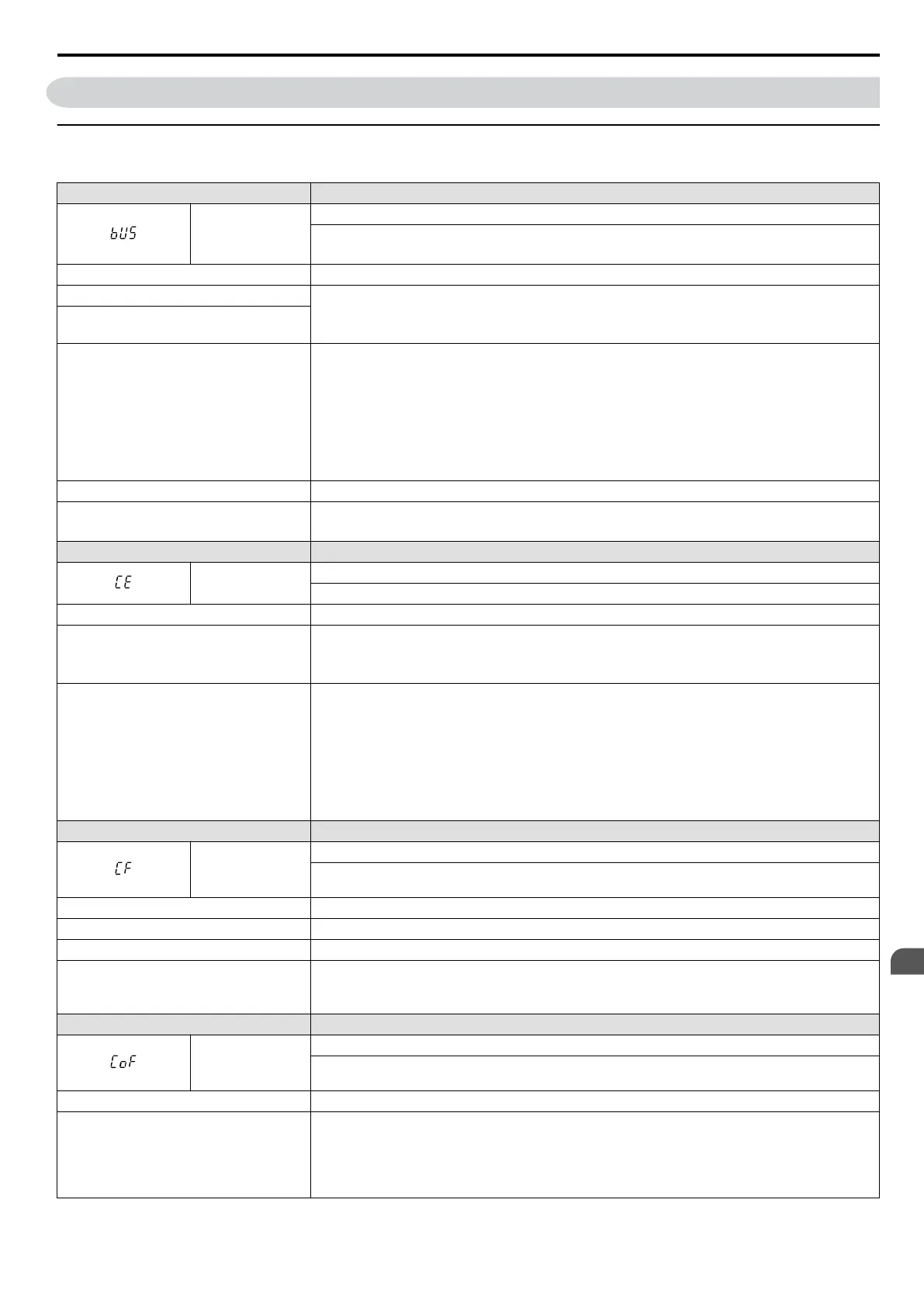
Table 6.9 Detailed Fault Displays, Causes, and Possible Solutions
LED Operator Display Fault Name
bUS
Option Communication Error
• After establishing initial communication, the connection was lost.
• Only detected when the run command frequency reference is assigned to an option card.
Cause Possible Solution
No signal received from the PLC. • Check for faulty wiring.
• Correct the wiring.
• Check for loose wiring and short circuits. Repair as needed.
The communication cable is faulty or a short
circuit exists.
A communications data error occurred due to
noise.
• Check the various options available to minimize the effects of noise.
• Counteract noise in control circuit, main circuit, and ground wiring.
• Ensure that other equipment such as switches or relays do not cause noise and use surge suppressors
if required.
• Use cables recommended by Yaskawa or another type of shielded line. Ground the shield on the
controller side or on the drive input power side.
• Separate all wiring for communications devices from drive input power lines. Install an EMC noise
filter to the input side of the drive input power.
The option card is damaged. • Replace the option card if there are no problems with the wiring and the error continues to occur.
The option card is not properly connected to
the drive.
• The connector pins on the option card are not properly lined up with the connector pins on the drive.
• Reinstall the option card.
LED Operator Display Fault Name
CE
MEMOBUS/Modbus Communication Error
Control data was not received for the CE detection time set to H5-09.
Cause Possible Solution
Faulty communications wiring, or a short
circuit exists.
• Check for faulty wiring.
• Correct the wiring.
• Check for loose wiring and short circuits. Repair as needed.
A communications data error occurred due to
noise.
• Check the various options available to minimize the effects of noise.
• Counteract noise in control circuit, main circuit, and ground wiring.
• Use Yaskawa-recommended cables, or another type of shielded line. Ground the shield on the
controller side or on the drive input power side.
• Ensure that other equipment such as switches or relays do not cause noise and use surge suppressors
if required.
• Separate all wiring for communications devices from drive input power lines. Install an EMC noise
filter to the input side of the drive input power.
LED Operator Display Fault Name
CF
Control Fault
A torque limit was reached continuously for three seconds or longer during a ramp to stop while in
Open Loop Vector Control.
Cause Possible Solution
Motor parameters are not set properly. Check the motor parameter settings and repeat Auto-Tuning.
Torque limit is too low. Set the torque limit to the most appropriate setting (L7-01 through L7-04).
Load inertia is too big.
• Adjust the deceleration time (C1-02, -04, -06, -08).
• Set the frequency to the minimum value and interrupt the run command when the drive finishes
decelerating.
LED Operator Display Fault Name
CoF
Current Offset Fault
The current sensor is damaged or there was residual induction current in the motor (e.g., during sudden
deceleration or when coasting) when the drive attempted to start the motor.
Cause Possible Solution
Due to residual induction current in the
motor when the drive attempted to start the
motor, the drive attempted to adjust the
current offset value beyond the allowable
range.
• Create a motor restart sequence that allows enough time for the residual induction voltage to
dissipate.
• Enable Speed Search at start (b3-01 = 1). Use the multi-function terminals to execute External Speed
Search 1 and 2 (H1-oo = 61 or 62).
Note: When using a PM motor, both External Speed Search 1 and 2 perform the same operation.
6.4 Fault Detection
YASKAWA ELECTRIC SIEP C710606 16C YASKAWA AC Drive – V1000 Technical Manual
253
6
Troubleshooting

 Loading...


