n
Low Voltage Wiring for Control Circuit Terminals
Wire
low voltage wires with NEC Class 1
circuit conductors. Refer to national state or local codes for wiring. The external
power supply shall be a UL-Listed Class 2 power source or equivalent.
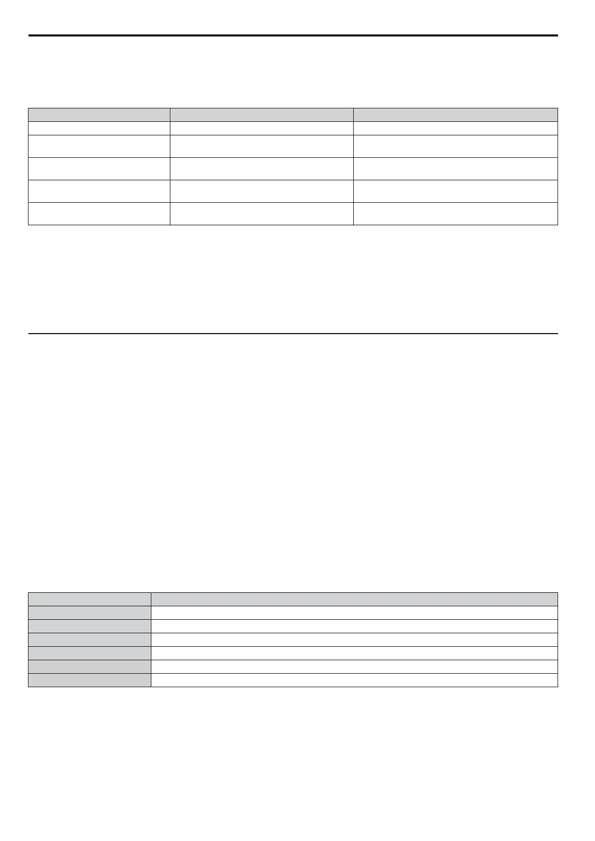
Table D.11 Control Circuit Terminal Power Supply
Input / Output Terminal Signal Power Supply Specifications
Multi-function photocoupler output P1, P2, PC Requires class 2 power supply
Multi-function digital inputs S1, S2, S3, S4, S5, S6, S7, SC
Use the internal power supply of the drive. Use class 2
for external power supply.
Multi-function analog inputs A1, A2, AC
Use the internal power supply of the drive. Use class 2
for external power supply.
Pulse train input RP
Use the internal LVLC power supply of the drive. Use
class 2 for external power supply.
Pulse train output MP
Use the internal LVLC power supply of the drive. Use
class 2 for external power supply.
n
Drive Short-Circuit Rating
This
drive has undergone the UL short-circuit test,
which certifies that during a short circuit in the power supply the current
flow will not rise above 31,000 amps maximum at 240 V for 200 V class drives and 480 V for 400 V class drives.
• The MCCB and breaker protection and fuse ratings shall be equal to or greater than the short-circuit tolerance of the
power supply being used.
• Suitable for use on a circuit capable of delivering not more than 31,000 RMS symmetrical amperes for 240 V in 200 V
class drives (up to 480 V for 400 V class drives) motor overload protection.
u
Drive Motor Overload Protection
Set parameter E2-01 (motor rated current) to the
appropriate value to enable motor overload protection. The internal motor
overload protection is UL listed and in accordance with the NEC and CEC.
n
E2-01: Motor Rated Current
Setting Range: Model Dependent
Default Setting: Model Dependent
Parameter E2-01 (motor rated current) protects the motor if parameter L1-01 is not set to 0 (default is 1, standard induction
motor protection enabled).
If Auto-Tuning has been performed successfully, the motor data that was entered in T1-04 is automatically written into
parameter E2-01. If Auto-Tuning has not been performed, manually enter the correct motor rated current in parameter
E2-01.
n
L1-01: Motor Overload Protection Selection
The drive has an electronic overload protection function (oL1) based on time, output current and output frequency, which
protects the motor from overheating. The electronic thermal overload function is UL-recognized, so it does not require an
external thermal overload relay for single motor operation.
This parameter selects the motor overload curve used according to the type of motor applied.
Table D.12 Overload Protection Settings
Setting Description
0 Disabled
1 Standard Fan-Cooled Motor (Default)
2 Drive Duty Motor with a Speed Range of 1:10
3 Vector Motor with a Speed Range of 1:100
4 Permanent Magnet Motor with Variable Torque
6 Standard Fan-Cooled Motor (50 Hz)
Disable the electronic overload protection (L1-01 = 0: Disabled) and wire each motor with its own motor thermal overload
when connecting the drive to more than one motor for simultaneous operation.
Enable the motor overload protection (L1-01 = “1”,
“2”, or “3”) when connecting the drive to a single motor unless there
is another means of preventing motor thermal overload. The electronic thermal overload function causes an oL1 fault,
which shuts off the output of the drive and prevents additional overheating of the motor. The motor temperature is
continually calculated as long as the drive is powered up.
Setting L1-01 = 1 selects a motor with limited cooling capability below rated (base) speed when running at 100% load.
The oL1 function derates the motor when it is running below base speed.
D.3 UL Standards
448
YASKAWA ELECTRIC SIEP C710606 16C YASKAWA AC Drive – V1000 Technical Manual

 Loading...


