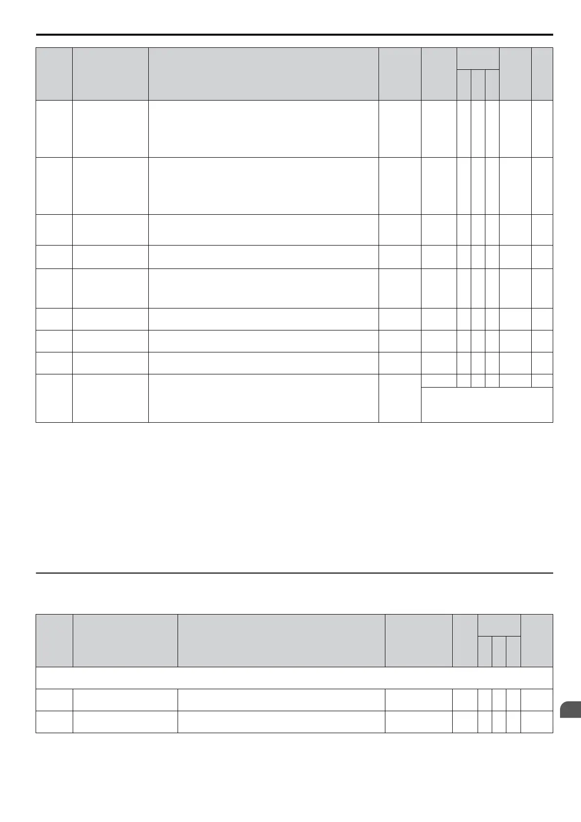
No. Name Description Range Def.
Control
Mode
Addr.
Hex
Pg.
V/
f
O
L
V
P
M
T1-00
Motor Selection
1/2
Selects which set of motor parameters are used and set during
Auto-Tuning. If Motor 2 selection (H1-oo = 16) is not selected,
this parameter will not be displayed.
1: Motor 1 (sets E1-oo, E2-oo)
2: Motor 2 (sets E3-oo, E4-oo. This selection is not displayed
if motor 2 has not been selected.)
1, 2 1 A A − 700 104
T1-01
Auto-Tuning Mode
Selection
Selects the Auto-Tuning mode.
0: Rotational Auto-Tuning
2: Stationary Auto-Tuning for Line-to-Line Resistance
3:
Rotational Auto-Tuning for V/f Control (necessary for Energy
Savings and Speed Estimation type Speed Search)
0, 2, 3
<1>
2 or 3 in
V/f
0 or 2 in
OLV
2 in
Motor 2
A A − 701 104
T1-02 Motor Rated Power
Sets the motor rated power in kilowatts (kW).
Note: If motor power is given in horsepower, power in kW can
be calculated using the following formula: kW = HP x 0.746.
<2> <3>
A A − 702 104
T1-03
<4>
Motor Rated
Voltage
Sets the motor rated voltage in volts (V).
0.0 to
255.5
200.0 V A A − 703 104
T1-04
Motor Rated
Current
Sets the motor rated current in amperes (A).
10 to
200% of
drive rated
current
<3>
A A − 704 104
T1-05
Motor Base
Frequency
Sets the base frequency of the motor in Hertz (Hz).
0.0 to
400.0
<5>
A A − 705 105
T1-06
Number of Motor
Poles
Sets the number of motor poles. 2 to 48 4 A A − 706 105
T1-07 Motor Base Speed
Sets the base speed of the motor in revolutions per minute r/min
(RPM).
0 to 24000
<6>
A A − 707 105
T1-11 Motor Iron Loss
Provides the iron loss for determining the Energy Saving
coefficient.
The
value set to E2-10 (motor iron loss)
when the power is cycled.
If T1-02 is changed, an initial value valid for the selected capacity
will be shown.
0 to 65535
14 W A − − 70B 105
These values differ depending on the
motor code value and motor
parameter settings.
<1> The available tuning methods depend on control mode. Select values 2 or 3 in V/f Control, 0 or 2 in OLV control, and 2 for Motor 2 control.
<2> Setting range varies depending on drive software version.
PRG: 1016 and later: 0.03 to 650.00 kW
PRG: 1015 and earlier: 0.00 to 650.00 kW
<3> Default setting value is dependent on parameter o2-04, Drive Model Selection.
<4> Values shown here are for 200 V class drives. Double the value when using a 400 V class drive.
<5> Regional default settings:
Setting 60.0 Hz: Japan (Model code: CIMR-VAoA) and Asia (Model code: CIMR-VToA)
Setting 50.0 Hz: China (Model code: CIMR-VBoA)
<6> Regional default settings:
Setting 1750 r/min: Japan (Model code: CIMR-VAoA) and Asia (Model code: CIMR-VT
oA)
Setting 1450 r/min: China (Model code: CIMR-VBoA)
u
U: Monitors
Monitor parameters allow the user to view drive status, fault information, and other information about drive operation.
No. Name Description
Analog Output
Level
Unit
Control
Mode
Addr.
Hex
V/
f
O
L
V
P
M
U1: Operation Status Monitors
Use U1 monitors to display the operation status of the drive.
U1-01 Frequency Reference Monitors the frequency
10 V: Max
frequency
0.01
Hz
A A A 40
U1-02 Output Frequency
Displays the output frequency. Display units are
determined by o1-03.
10 V: Max
frequency
0.01
Hz
A A A 41
B.2 Parameter Table
YASKAWA ELECTRIC SIEP C710606 16C YASKAWA AC Drive – V1000 Technical Manual
371
B
Parameter List

 Loading...


