u
n: Advanced Performance Set-Up
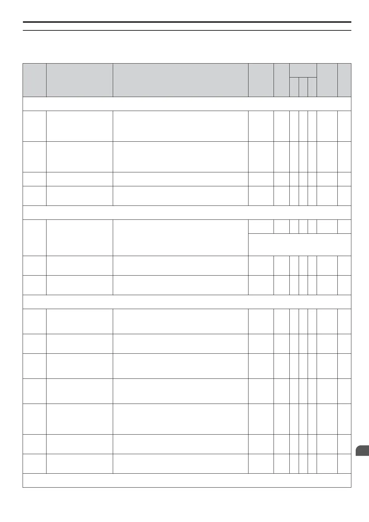
The n parameters are used to adjust more
advanced performance characteristics such as hunting prevention, speed feedback
detection, high-slip braking and R1 online tuning.
No. Name Description Range Def.
Control
Mode
Addr.
Hex
Pg.
V/
f
O
L
V
P
M
n1: Hunting Prevention
Use n1 parameters to configure hunting prevention operation.
n1-01
Hunting Prevention
Selection
If the motor vibrates while lightly loaded, Hunting
Prevention may reduce the vibration.
0: Disabled
1: Enabled
When quick response is needed disable Hunting Prevention.
0, 1 1 A − − 580 229
n1-02
Hunting Prevention Gain
Setting
Sets the gain for the Hunting Prevention Function.
If the motor vibrates while lightly loaded and n1-01 = 1,
increase the gain by 0.1 until vibration ceases.
If the motor stalls while n1-01 = 1, decrease the gain by 0.1
until the stalling ceases.
0.00 to
2.50
1.00 A − − 581 229
n1-03
Hunting Prevention Time
Constant
Sets the time constant used for hunting prevention. 0 to 500
<1>
A − − 582 229
n1-05
Hunting Prevention Gain
while in Reverse
Sets the gain used for Hunting Prevention.
When set to 0, the gain n1-02 is used for operation in reverse
direction.
0.00 to
2.50
0.00 A − − 530 229
n2: Speed Feedback Detection Control Function
Use n2 parameters to configure the Speed Feedback Detection Control function operation.
n2-01
Speed Feedback Detection
Control (AFR) Gain
Sets the internal speed feedback detection control gain in the
automatic frequency regulator (AFR).
This parameter does not typically require adjustment. Adjust
this parameter as follows:
If hunting occurs, increase the set value.
If response is low, decrease the set value.
0.00 to
10.00
<8>
− A − 584 229
Adjust the setting by 0.05 units at a time,
while checking the response.
n2-02
Speed Feedback Detection
Control (AFR) Time
Constant
Sets the AFR time constant 1. 0 to 2000 50 ms − A − 585 230
n2-03
Speed Feedback Detection
Control (AFR) Time
Constant 2
Sets the AFR time constant 2. Increase the setting if
overvoltage occurs during sudden load changes or the speed
overshoots during fast acceleration.
0 to 2000
750
ms
− A − 586 230
n3: High-Slip Braking
Use n3 parameters to configure the high-slip braking function.
n3-01
High-Slip Braking
Deceleration Frequency
Width
Sets the output frequency reduction step width when the
drive stops the motor using high-slip braking (HSB).
If Overvoltage (ov) faults occur during HSB, this parameter
may need to be increased.
1 to 20 5% A − − 588 230
n3-02
High-Slip Braking Current
Limit
Sets the current limit during HSB. Higher n3-02 settings will
shorten motor stopping times but increase the motor current,
and therefore motor heating.
100 to
200
150% A − − 589 230
n3-03
High-Slip Braking Dwell
Time at Stop
Sets the time the drive will run with minimum frequency
(E1-09) at the end of deceleration.
If this time is set too low, the machine inertia can cause the
motor to rotate slightly after HSB completion.
0.0 to
10.0
1.0 s A − − 58A 231
n3-04
High-Slip Braking Overload
Time
Sets the time required for an HSB overload fault (oL7) to
occur when the drive output frequency does not change
during an HSB stop. This parameter does not typically
require adjustment.
30 to
1200
40 s A − − 58B 231
n3-13
Overexcitation Deceleration
Gain
Applies a gain to the V/f pattern during deceleration (L3-04
= 4). Returns to normal values after ramp to stop or at re-
acceleration.
To increase the braking power of overexcitation, increase the
gain by 1.25 to 1.30.
1.00 to
1.40
1.10 A A − 531 231
n3-21
High-Slip Suppression
Current Level
If overcurrent or overload occur during high-slip
deceleration, reduce the high-slip suppression current level.
Set as a percentage of the drive rated current.
0 to 150 100% A A − 579 231
n3-23
Overexcitation Operation
Selection
0: Enabled in both directions
1: Enabled only when rotating forward
2: Enabled only when in reverse
0 to 2 0 A A − 57B 231
n6: Online Tuning of Motor Line-to-Line Resistance
Use n6 parameters to adjust the motor line-to-line resistance while the drive is online.
B.2 Parameter Table
YASKAWA ELECTRIC SIEP C710606 16C YASKAWA AC Drive – V1000 Technical Manual
365
B
Parameter List

 Loading...


