4.2 Using the Digital LED Operator
Use the LED operator to enter run and stop commands, display data, edit parameters, as well as display fault and alarm
information.
u
Keys, Displays, and LEDs
STOP
(
Hz
)
(
Hz
)
(
A
)
(
V
)
:
:
:
:
:
:
:
:
:
:
Fref
FWD/REV Sel
Fout
lout
Mon1
Monitor
Verify
SetUpGuide
Program
Auto-Tuning
Read manual before installing.
Risk of electric shock.
Wait 1 minute for capacitor discharge after
disconnecting power supply.
To conform to requirements, make sure to
ground the supply neutral for 400V class.
WARNING
V1000
9
5
1
2
3
4 6
7
8
10
11
12
13
15
14
16
STOP
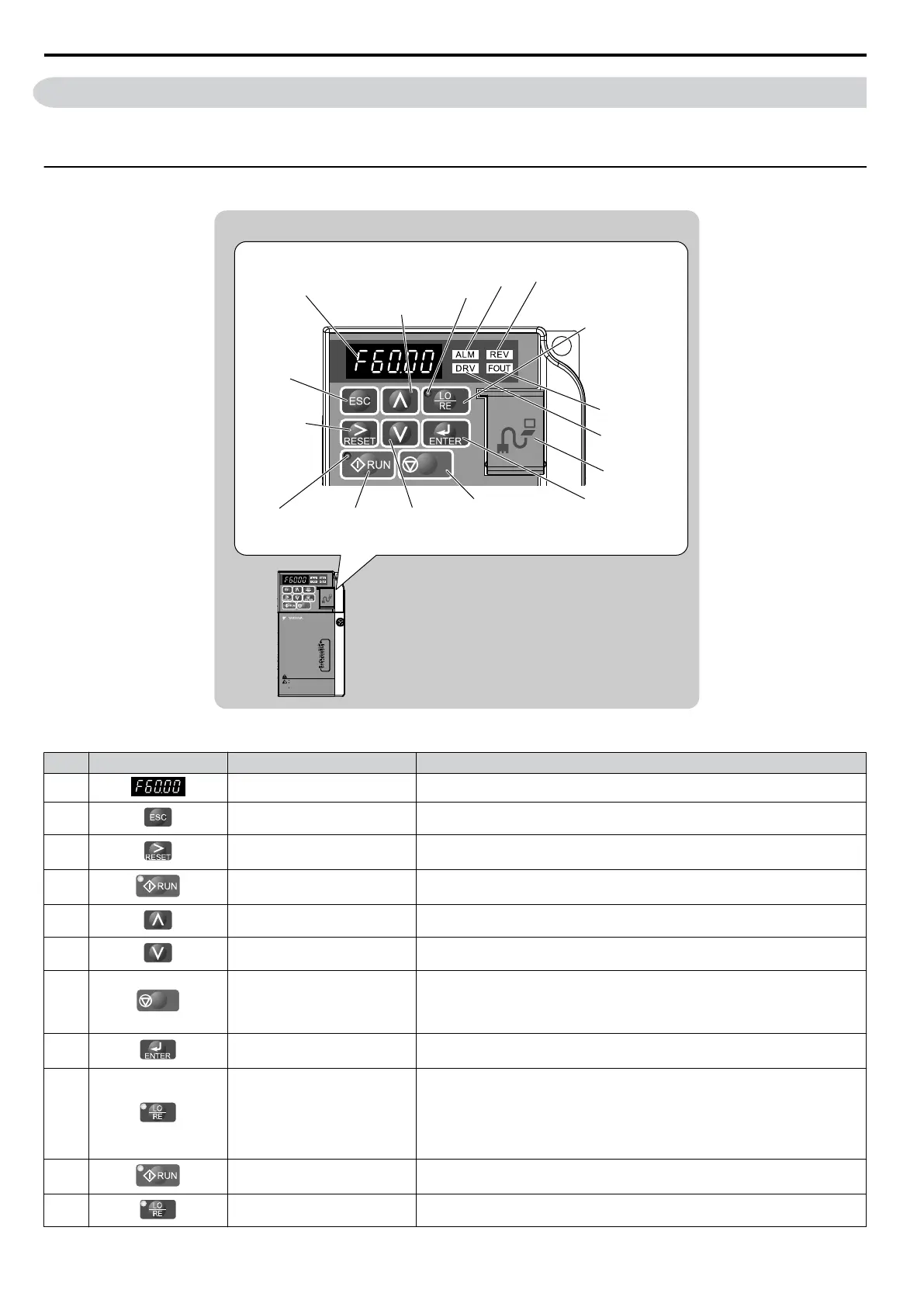
Table 4.1 Keys and Displays on the LED Operator
No. Display Name Function
1
Data Display Area Displays the frequency reference, parameter number, etc.
2 ESC Key Returns to the previous menu.
3 RESET Key
Moves the cursor to the right.
Resets the drive to clear a fault situation.
4
RUN Key Starts the drive.
5
Up Arrow Key Scrolls up to select parameter numbers, setting values, etc.
6 Down Arrow Key Scrolls down to select parameter numbers, setting values, etc.
7
STOP
STOP Key
Stops the drive.
Note: Stop priority circuit. Pressing the STOP key will always cause the drive
to stop the motor, even when a Run command is active at an external Run
command source. Set parameter o2-06 to 0 to disable the STOP key priority.
8 ENTER Key
Selects all modes, parameters, settings, etc.
Selects a menu item to move from one display screen to the next.
9 LO/RE Selection Key
Switches drive control between the operator (LOCAL) and the control circuit
terminals (REMOTE).
Note: LOCAL/REMOTE key effective during stop in drive mode. If the digital
operator could change from REMOTE to LOCAL by incorrect operation, set
o2-01 (LOCAL/REMOTE Key Function Selection) to “0” (disabled) to disable
LOCAL/REMOTE key.
10 RUN Light Lit while the drive is operating the motor.
11 LO/RE Light Lit while the operator (LOCAL) is selected to run the drive.
4.2 Using the Digital LED Operator
78
YASKAWA ELECTRIC SIEP C710606 16C YASKAWA AC Drive – V1000 Technical Manual

 Loading...


