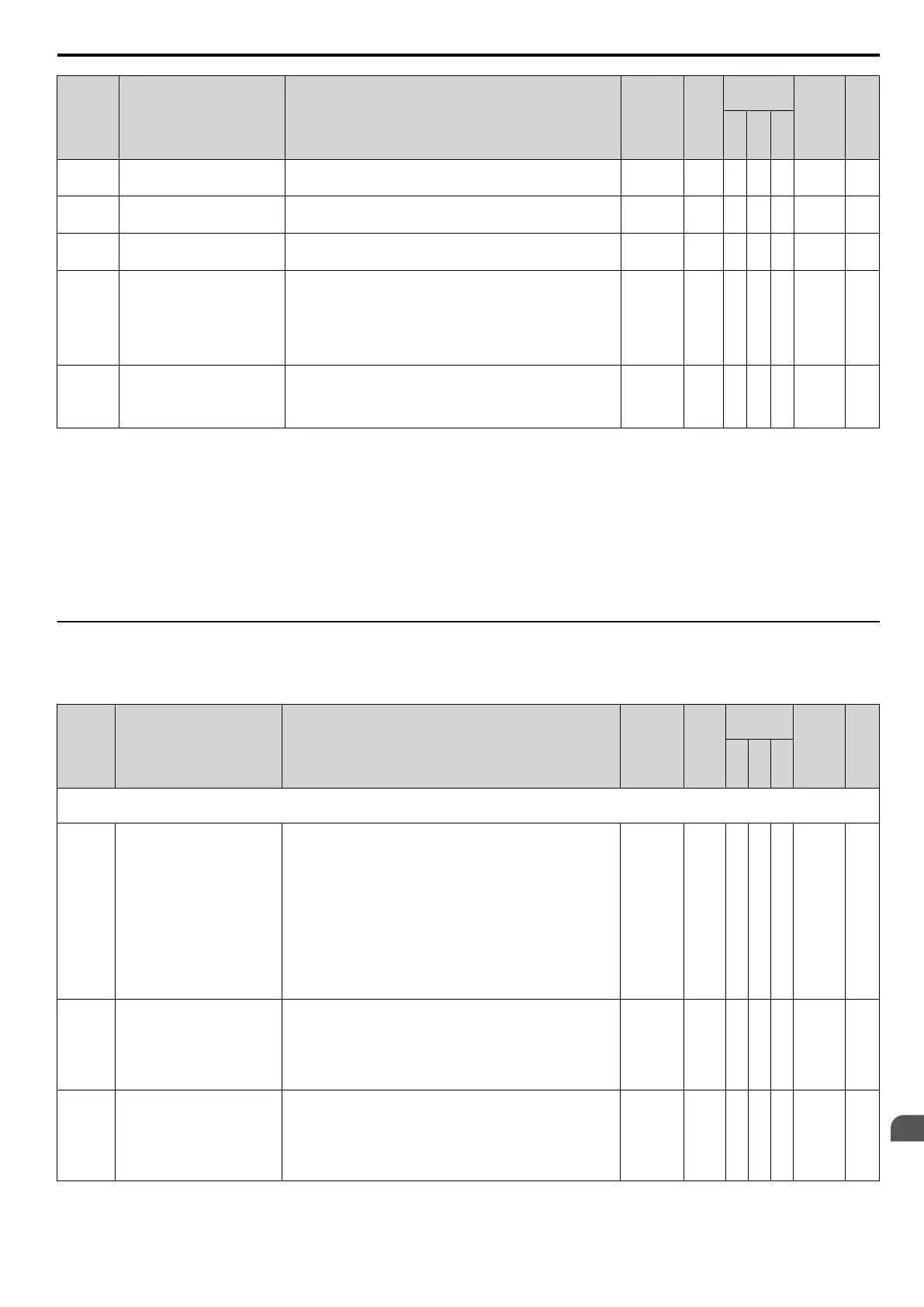
No. Name Description Range Def.
Control
Mode
Addr.
Hex
Pg.
V/
f
O
L
V
P
M
H6-03
<2>
Pulse Train Input Gain
Sets the level of the value selected in H6-01 when a
frequency with the value set in H6-02 is input.
0.0 to
1000.0
100.0
%
A A A 42E 202
H6-04
<2>
Pulse Train Input Bias
Sets the level of the value selected in H6-01 when 0 Hz is
input.
-100.0 to
+100.0
0.0% A A A 42F 202
H6-05
<2>
Pulse Train Input Filter Time
Sets the pulse train input filter time constant.
0.00 to
2.00
0.10 s A A A 430 202
H6-06
<2>
Pulse Train Monitor
Terminal MP Selection
Select the pulse train monitor output function (value of the
o-oo part of Uo-oo).
Refer
to U: Monitors on page 371
for the list of U monitors.
Example: To select U5-01, set “501. ”When not using this
parameter or when using in the through mode, set “000”.
<5>
000, 031,
101, 102,
105, 116,
501, 502;
801 to
809
102 A A A 431 202
H6-07
<2>
Pulse Train Monitor
Scaling
Sets the terminal MP output signal frequency when the
monitor
value is 100%. Set H6-06 to 102
and H6-07 to 0 to
make the pulse train monitor output equal to the output
frequency.
0 to
32000
1440
Hz
A A A 432 202
<1> The availability of certain functions depends on the control method used.
<2> Parameter can be changed during Run.
<3> If this parameter is set to 0, the drive will be unable to respond to MEMOBUS/Modbus commands.
<4> Default setting is determined by drive software version.
PRG: 1016 and later: 100 to 32000 Hz
PRG: 1015 and earlier: 1000 to 32000 Hz
<5>
When set for sourcing, +5
V/1.5 kΩ or higher, +8 V/3.5 kΩ or higher, +10 V/10 kΩ or higher. When set for sinking, the external power supply
should be +12 Vdc, ±5% with 16 mA or less.
Note: Cycle power to the drive to enable MEMOBUS/Modbus settings.
u
L: Protection Function
L parameters provide protection to the drive and motor, such as: control during momentary power loss, Stall Prevention,
frequency detection, fault restarts, overtorque detection, torque limits and other types of hardware protection.
No. Name Description Range Def.
Control
Mode
Addr.
Hex
Pg.
V/
f
O
L
V
P
M
L1: Motor Protection Functions
Use L1 parameters to configure motor protective functions.
L1-01
Motor Overload Protection
Selection
Sets the motor thermal overload protection (oL1) based on
the cooling capacity of the motor.
0: Disabled
1: General Purpose Motor (Standard Fan Cooled)
2: Drive Dedicated Motor with a Speed Range of 1:10
3: Vector Motor with a Speed Range of 1:100
4: PM Motor with Variable Torque
6: General Purpose Motor (50 Hz)
<1>
Note:
When using multiple motors the drive may
not be able
to provide protection, even if overload is enabled in L1-01.
Set L1-01 to 0 and ensure each motor has separate thermal
relays installed.
0 to 4; 6
1
<2>
S S S 480 203
L1-02
Motor Overload Protection
Time
Sets the motor thermal overload protection (oL1) time.
A larger L1-02 time will increase the time for an oL1 fault
to occur.
This parameter does not typically require adjustment.
Should be set in accordance with the overload tolerance of
the motor.
0.1 to 5.0
1.0
min
A A A 481 205
L1-03
Motor Overheat Alarm
Operation Selection (PTC
input)
Sets operation when the motor temperature analog input
(H3-02/10 = E) exceeds the oH3 alarm level.
0: Ramp to Stop
1: Coast to Stop
2: Fast-stop using C1-09
3: Alarm Only (“oH3” will flash)
0 to 3 3 A A A 482 206
B.2 Parameter Table
YASKAWA ELECTRIC SIEP C710606 16C YASKAWA AC Drive – V1000 Technical Manual
357
B
Parameter List

 Loading...


