Overload Tolerance Cooling Ability Overload Characteristics
A: Max. speed for 200LJ and above
B: Max. speed for 160MJ to 180 LJ
C: Max. speed for 132MJ and below
05 33 100 120 167 200
Speed (%)
Continuous
A
B
C
Rated Speed=100% Speed
60 s
150
100
90
60
50
Torque (%)
Motor designed to operate from line
power. Motor cooling is most
effective when running at rated base
frequency (check the motor
nameplate or specifications)
Continuous operation at less than line
power frequency with 100% load can
trigger motor overload protection
(oL1). A fault
is output and the motor
will coast to stop.
n
L1-02: Motor Overload Protection Time
Sets
the time for the drive to shut
down on motor overload (oL1) when the motor is running with excessive current. Enter
the time the motor can withstand operating at 150% current after previously running at 100% current (hot motor overload
condition). This parameter rarely requires adjustment.
No. Name Setting Range Default
L1-02 Motor Overload Protection Time 0.1 to 5.0 minutes 1.0 minutes
Defaulted to operate with an allowance of 150% overload operation for one minute in a hot start after continuous operation
at 100%.
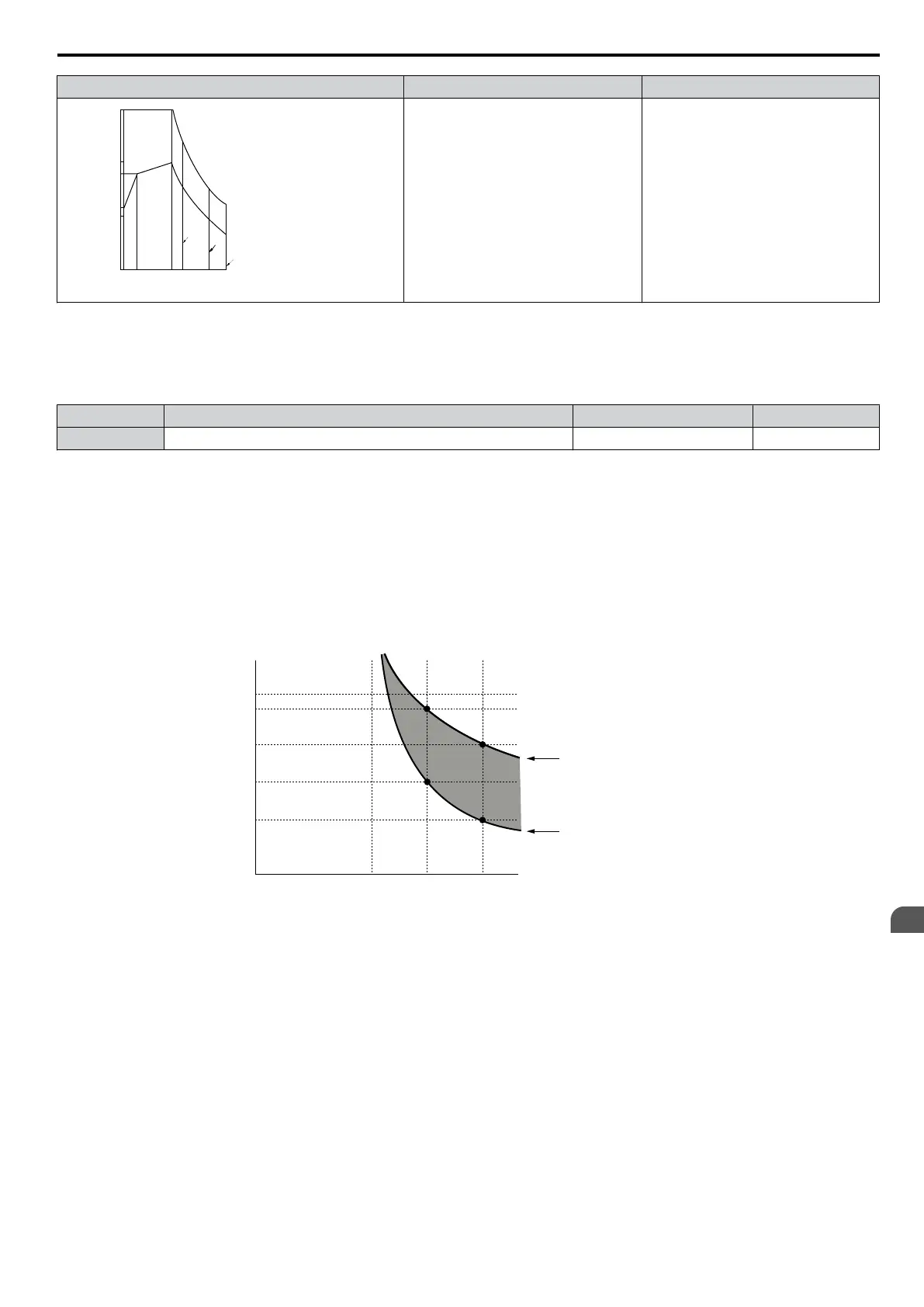
Figure 5.76 illustrates an example of the
electrothermal protection operation time using a general-purpose motor operating
at the value of E1-06, Motor Base Speed, with L1-02 set to one minute.
Motor overload protection operates in the area between a cold start and a hot start.
• Cold start: Characteristics of motor protection operation time in response to an overload situation that was suddenly
reached when starting a stationary motor.
• Hot start: Characteristics of motor protection operation time in response to an overload situation that occurred while the
motor was operating continuously at or below its rated current.
Operation time (minutes)
Cold start
(characteristics when an
overload occurs at a
complete stop)
Hot start
(characteristics when an
overload occurs during
continuous operation at 100%)
Motor current (%)
E2-01 = 100% motor current
10
7
3
1
0.4
0.1
0 100 150 200
Figure 5.76 Protection Operation Time for General Purpose Motors at the Rated Output Frequency
n
Motor Protection Using a Positive Temperature Coefficient (PTC)
A
motor PTC can be connected to an
analog input of the drive. This input is used by the drive for motor overheat protection.
When the motor overheat alarm level is reached, an oH3 alarm will be triggered and the drive will continue operation as
selected in L1-03. When the overheat fault level is reached an oH4 fault is triggered, a fault signal will be output and the
drive will stop the motor using the stop method determined in L1-04.
Figure 5.77 shows a PTC connection example for analog input A2. If using analog input A2, make sure to set DIP switch
S1 on the terminal board for voltage input when using this function.
5.8 L: Protection Functions
YASKAWA ELECTRIC SIEP C710606 16C YASKAWA AC Drive – V1000 Technical Manual
205
5
Parameter Details

 Loading...


