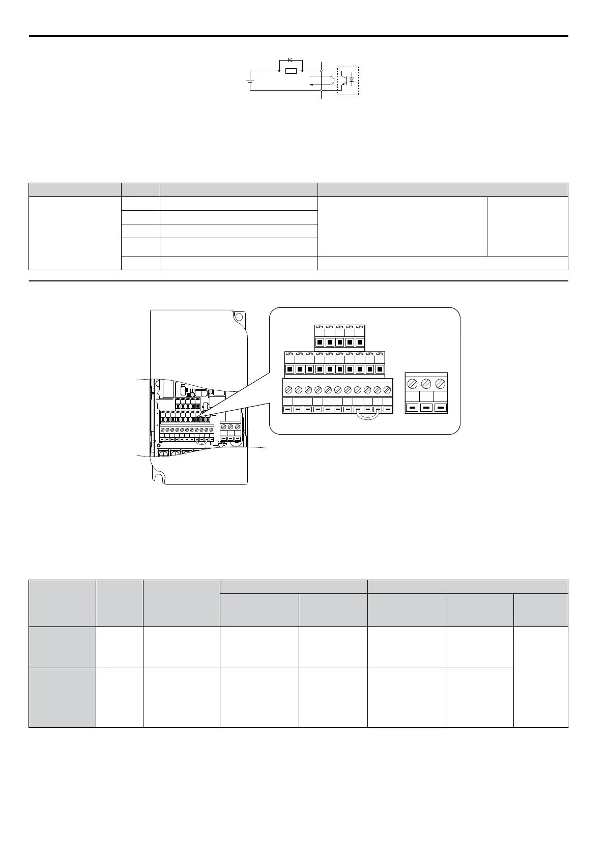
A
B
C
D
A – External power, 48 V max.
B – Suppression diode
C – Coil
D – 50 mA or less
Figure 3.17 Connecting a Suppression Diode
n
Serial Communication Terminals
Table 3.8 Control Circuit Terminals: Serial Communications
Type No. Signal Name Function (Signal Level)
MEMOBUS/Modbus
Communication
R+ Communications input (+)
MEMOBUS/Modbus communication: Use a
RS-485 or RS-422 cable to connect the drive.
RS-485/422
MEMOBUS/
Modbus
communication
protocol 115.2 kbps
(max.)
R-
Communications input (-)
S+ Communications output (+)
S- Communications output (-)
IG Shield ground 0 V
u
Terminal Configuration
S1 S2 S3 S4 S5 S6 S7 HC SC H1 RP
R+ R– S+ S– IG
P1 P2 PC A1 A2 +V AC AM AC MP
MCMBMA
S1 S2 S3 S4 S5 S6 S7 HC SC H1 RP
R+ R- S+ S- IG
P1 P2 PC A1 A2 +V AC AM AC MP
MCMBMA
Figure 3.18 Removable Control Circuit Terminal Block
n
Wire Size and Torque Specifications
Select
appropriate wire type and size from Table 3.9. For simpler and more reliable wiring, crimp ferrules to the wire ends.
Refer to Table 3.10 for ferrule terminal types and sizes.
Table 3.9 Wire Size and Torque Specifications (Same for All Models)
Terminal
Screw
Size
Tightening
Torque
N•m
(in-lbs)
Bare Wire Terminal Ferrule-Type Terminal
Applic. wire size
mm
2
(AWG)
Recomm. mm
2
(AWG)
Applic. wire size
mm
2
(AWG)
Recomm.
mm
2
(AWG)
Wire Type
MA, MB, MC M3
0.5 to 0.6
(4.4 to 5.3)
Stranded: 0.25 to 1.5
(24 to 16)
Single: 0.25 to 1.5
(24 to 16)
0.75 (18)
0.25 to 1.0
(24 to 17)
0.5 (20)
Shielded line,
etc.
S1-S7, SC, RP,
+V, A1, A2, AC,
HC, H1, P1, P2,
PC, MP, AM,
AC, S+, S-, R+,
R-, IG
M2
0.22 to 0.25
(1.9 to 2.2)
Stranded: 0.25 to 1.0
(24 to 18)
Single: 0.25 to 1.5
(24 to 16)
0.75 (18)
0.25 to 0.5
(24 to 20)
0.5 (20)
3.7 Control Circuit Wiring
64
YASKAWA ELECTRIC SIEP C710606 16C YASKAWA AC Drive – V1000 Technical Manual

 Loading...


