n
V/f Pattern Settings E1-04 to E1-13
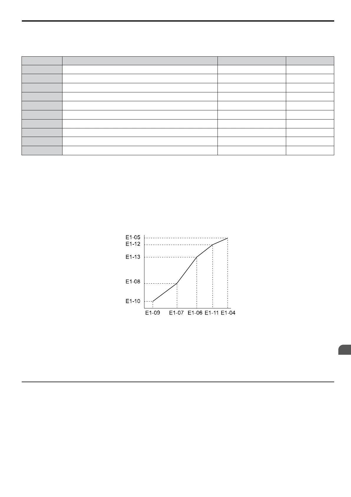
Using
parameters E1-04 through E1-13, the user can
either monitor the V/f pattern values if E1-03 =< 15 or set up a custom
V/f pattern as shown in Figure 5.42 when E1-03 = F.
No. Parameter Name Setting Range Default
E1-04 Maximum Output Frequency
40.0 to 400.0 Hz
<5> <1> <6>
E1-05 Maximum Voltage
0.0 to 255.0 V
<2> <1>
E1-06 Base Frequency
0.0 to 400.0 Hz
<5> <1> <6>
E1-07 Middle Output Frequency 0.0 to 400.0 Hz
<1> <6>
E1-08 Middle Output Frequency Voltage
0.0 to 255.0 V
<2> <1>
E1-09
<3>
Minimum Output Frequency
0.0 to 400.0 Hz
<5> <1> <6>
E1-10 Minimum Output Frequency Voltage
0.0 to 255.0 V
<2> <1>
E1-11 Middle Output Frequency 2 0.0 to 400.0 Hz 0.0 Hz
E1-12 Middle Output Frequency Voltage 2
0.0 to 255.0 V
<2>
0.0 V
E1-13
<4>
Base Voltage 0.0 to 255.0 Hz 0.0 V
<1> Default setting is determined by the control mode.
<2> Values shown are for 200 V class drives; double the value when using 400 V class drives.
<3> In OLV for PM E1-09 specifies
the start frequency for short circuit braking at stop. Refer to b2-13: Short Circuit Brake Time at Stop on page
125 for details.
<4> When E1-13 is set to 0.0 V, the drive uses the value set in E1-05 to control the voltage.
<5> Default setting is determined by E5-01 in OLV/PM. When E5-01 is set to FFFFH, the setting range for E1-04 and E1-06 is 10.0 to 40.0 Hz
and the setting range for E1-09 is 0.0 to 400.0 Hz.
<6>
The default value is for the following localized drives: Japan (Model code: CIMR-VAoA) and Asia (Model code: CIMR-VToA). Refer to
China Localized Drive Default Values on page 381 for the default values of China localized (Model code: CIMR-VBoA) drives.
Output Voltage (V)
Frequency (Hz)
Figure 5.42 V/f Pattern
Note: 1. The following condition must be true when setting up the V/f pattern: E1-09 ≤ E1-07 < E1-06 ≤ E1-11 ≤ E1-04
2. Setting E1-11 to 0 disables both E1-11 and E1-12 and the above conditions do not apply.
3. To make the V/f pattern a straight line set E1-09 = E1-07. In this case the E1-08 setting is disregarded.
4. E1-03 is unaffected when the drive is initialized using parameter A1-03, but the settings for E1-04 through E1-13 are returned to
their default values.
u
E2: Motor 1 Parameters
These parameters contain the most important motor data needed for optimal motor control. They are set automatically
when Auto-Tuning is performed. If Auto-Tuning can not be performed, then these parameters can be set manually.
n
E2-01: Motor Rated Current
Set E2-01 to the full load amps (FLA) stamped on the motor nameplate. During Auto-Tuning the value must be entered
to parameter T1-04. If Auto-Tuning completes successfully, the value entered will automatically be saved to E2-01.
5.5 E: Motor Parameters
YASKAWA ELECTRIC SIEP C710606 16C YASKAWA AC Drive – V1000 Technical Manual
165
5
Parameter Details

 Loading...


